PLCopen Motion Control
The PLCopen* motion standard provides a way to have standard application libraries that are reusable for multiple hardware platforms. It is widely accepted in the industrial control market for the CNC, robotics, and motion control applications. For more detailed information of the PLCopen motion specifications, refer to Motion Control.
Install PLCopen Motion Control
You can install this component from the ECI APT repository. Setup the ECI APT repository, then perform either of the following commands to install this component:
- Install from meta-package
$ sudo apt install eci-softplc-plcopen
- Install from individual Deb package
# For non-Xenomai kernels
$ sudo apt install plcopen-motion plcopen-servo plcopen-databus \
  plcopen-ruckig plcopen-openplc-runtime plcopen-openplc-editor

# For Xenomai kernels
$ sudo apt install plcopen-motion-xenomai plcopen-servo-xenomai plcopen-databus-xenomai \
  plcopen-ruckig plcopen-openplc-runtime plcopen-openplc-editor
Install PLCopen Motion Control Development Headers
This component also provides header files for development use. Setup the ECI APT repository, then perform the following command to install this component:
- Install from individual Deb package
# For non-Xenomai kernels
$ sudo apt install plcopen-motion-dev plcopen-servo-dev plcopen-ruckig-dev

# For Xenomai kernels
$ sudo apt install plcopen-motion-xenomai-dev plcopen-servo-xenomai-dev plcopen-ruckig-dev
PLCopen Motion Function Blocks
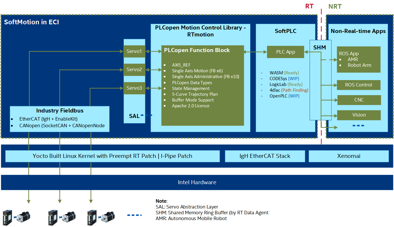
In Intel® Edge Controls for Industrial (Intel® ECI), the PLCopen motion control library RTmotion is used with the IgH EtherCAT Master Stack and SoftPLC to create general motion control applications. RTmotion is an open source C++ library created by Intel®. RTmotion implements parts 1 and 2 of PLCopen motion control standard. With the extensions of machine vision and ROS2 functions, RTmotion function blocks have been successfully deployed to control discrete automation equipment, autonomous mobile robots (AMR) and robotic arms. The following figure shows the connection RTmotion and other components in ECI.
Currently, RTmotion contains the following function blocks:
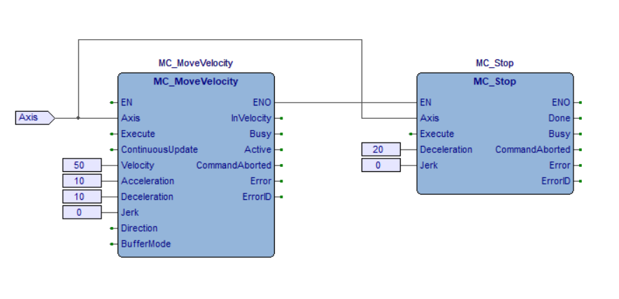
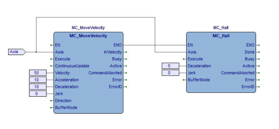
MC_Power: Controls the power stage (ON or OFF)MC_Stop: Commands a controlled motion stop and transfers the axis to theStoppingstateMC_Halt: Commands a controlled motion stop and transfers the axis to theStandStillstateMC_Reset: Makes the transition from theErrorStopstate to theStandstillorDisabledstate by resetting all internal axis-related errorsMC_MoveAbsolute: Commands a controlled motion to a specified absolute positionMC_MoveRelative: Commands a controlled motion of a specified distance relative to the set position at the time of the executionMC_MoveAdditive: Commands a controlled motion of a specified relative distance additional to the most recent commanded positionMC_MoveVelocity: Commands a never ending controlled motion at a specified velocityMC_ReadStatus: Returns, in detail, the status of the state diagram of the selected axisMC_ReadAxisError: Reads information concerning an axis, such as modes, inputs directly related to the axis, and certain status informationMC_ReadCommandPosition: Returns the command positionMC_ReadCommandVelocity: Returns the command velocityMC_ReadCommandAcceleration: Returns the command accelerationMC_ReadActualPosition: Returns the actual positionMC_ReadActualVelocity: Returns the actual velocityMC_ReadActualAcceleration: Returns the actual acceleration
Run multi-axis demonstration to execute one MC_MoveRelative function block for one axis:
$ /opt/plcopen/multi-axis -t 50 -i 250
Note: -t is used to set the running time in seconds. -i is used to set the real-time cycle time in microseconds.
The following sections provide detailed instructions on how to use the RTmotion function blocks to develop motion control applications for industrial automation and robotics.
Applications for Industrial Automation
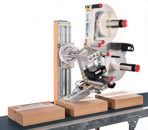
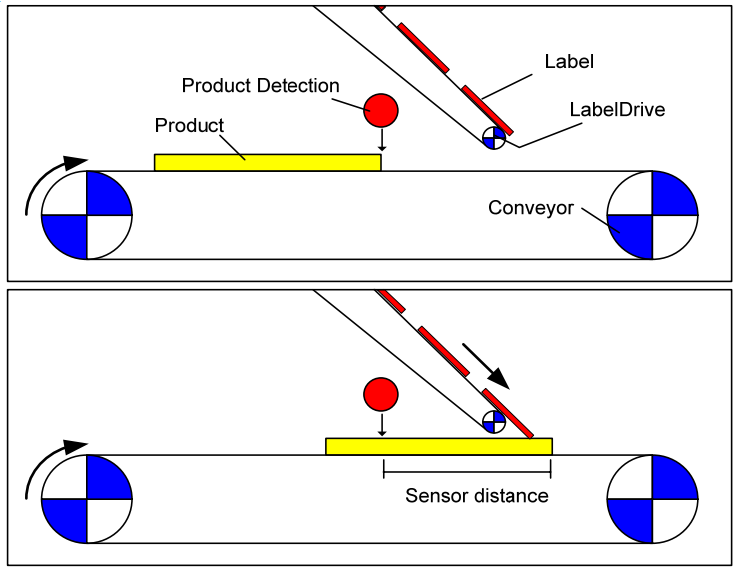
Labeling is commonly seen in the automation of the pharmaceuticals, beverage, and chemicals packaging. As shown in the following figures (left 1 and right 2), the task is to place a label at a particular position on a product. The application has two drives, one to feed the product via a conveyor belt and another to feed the labels and to place the labels on the products. The labeling process is triggered by a position detection sensor. From the detection of the product to the start of the label movement there is a delay depending on the velocity of the conveyor, the position of the sensor, and the position of the label on the product.
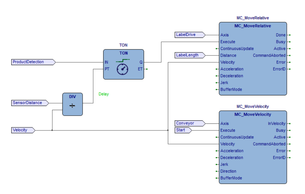
RTmotion motion control function blocks can be used with the SoftPLC systems, for example, CODESYS, MULTIPROG, and LogicLab, to solve this kind of problems. SoftPLC generally supports five programming languages for the application development according to the IEC 61131-3 standard: Instruction List (IL), Structured Text (ST), Function Block Diagram (FBD), Ladder Diagram (LD), and Sequential Function Chart (SFC). The following FBD 2 shows a way to solve this task. Both axes move with the same velocity setpoint. The delay for On Delay Timer (TON) is calculated from the sensor distance and the velocity. After a labeling step, the LabelDrive stops again and waits for the next trigger, while the conveyor continuously moves.
The labeling application can also be implemented as an ST program:
Click to view the ST program
(* PLC configuration *)
CONFIGURATION DefaultCfg
  VAR_GLOBAL
    Product_Detection   AT %MX3.0.0: BOOL;
    Start               AT %MX3.1.0: BOOL;
    Label_Length        AT %ML3.200: REAL;
    Sensor_Distance     AT %ML3.204: REAL;
    Velocity            AT %ML3.208: REAL;
  END_VAR

  // Schedule the main program to be executed every 1 ms
  TASK Tick(INTERVAL := T#1ms);

  PROGRAM Main WITH Tick : Labeling_Example_Code;
END_CONFIGURATION

(* Labeling machine program *)
PROGRAM Labeling_Example_Code
  VAR_EXTERNAL
    Product_Detection  : BOOL;
    Start              : BOOL;
    Label_Length:      : REAL;
    Sensor_Distance:   : REAL;
    Velocity           : REAL;
  END_VAR

  VAR
    MC_Power_1:         MC_Power;
    MC_Power_2:         MC_Power;
    Label_Drive:        AXIS_REF;
    Conveyor:           AXIS_REF;
    MC_MoveVelocity_1:  MC_MoveVelocity;
    MC_MoveRelative_1:  MC_MoveRelative;
    Delay_Timer:        TON;
  END_VAR

  MC_Power_1(Axis := Label_Drive,
            Enable := True,
            EnablePositive := True,
            EnableNegative := True);

  MC_Power_2(Axis := Conveyor,
            Enable := True,
            EnablePositive := True,
            EnableNegative := True);

  Delay_Timer(IN := Product_Detection,
              PT := REAL_TO_TIME(IN := Sensor_Distance / Velocity));

  IF MC_Power_1.Status AND MC_Power_1.Valid THEN
    MC_MoveRelative_1(Axis := Label_Drive,
                      Execute := Delay_Timer.Q,
                      Position := Label_Length,
                      Velocity := Velocity);
  END_IF;

  IF MC_Power_2.Status AND MC_Power_2.Valid THEN
    MC_MoveVelocity_1(Axis := Conveyor,
                      Execute := Start,
                      Velocity := Velocity);
  END_IF;
END_PROGRAM
A sample is provided in ECI, which converts the ST program into a C++ program and drives two Inovance EtherCAT servo motors. Run by the following command:
$ cd /opt/plcopen/duo_rtmotion_demo -n inovance_duo_1ms.xml -i 1000
where, -n specifies the EtherCAT ENI file, which is generated from a vendor-specific EtherCAT ESI file. For more information, refer to EtherCAT Enablekit. -i specifies the real-time cycle time in microseconds.
To run a real labeling application, input the FBD or ST program to the SoftPLC system, integrate the RTmotion function blocks with the SoftPLC system, and connect the function blocks to the servo motors through the IgH* EtherCAT master stack. Then, use the SoftPLC system to compile and run the program to control the labeling machine.
SoftPLC systems usually provide an interface to integrate external function blocks written in C or C++. The integration includes three steps:
Develop a new derived servo class from the
RTmotion/Servoclass. Override all the virtual functions of theRTmotion/Servoclass by using the SoftPLC provided EtherCAT master stack API to control a servo motor.Use SoftPLC SDK to create custom function blocks that match the input/output of
RTmotion::Function Blocks.Register the initialization of
RTmotion::Axes,RTmotion::Function BlocksandRTmotion::Derived Servosto the PLC initialization function. Register therunCyclefunctions ofRTmotion::AxesandRTmotion::Function Blocksto the PLC runtime functions.
When running the FBD or ST program, the function blocks will be called to send the trajectory planning commands to control the servo motors.
Implement the derived servo class as shown here:
#include <RTmotion/Servo.hpp>
class MyServo : public Servo
{
public:
    MyServo();
    virtual ~MyServo();

    virtual MC_ServoErrorCode setPower(bool powerStatus, bool& isDone) override;
    virtual MC_ServoErrorCode setPos(int32_t pos) override;
    virtual MC_ServoErrorCode setVel(int32_t vel) override;
    virtual MC_ServoErrorCode setTorque(double torque) override;
    virtual int32_t pos(void) override;
    virtual int32_t vel(void) override;
    virtual int32_t acc(void) override;
    virtual double torque(void) override;
    virtual bool readVal(int index, double& value) override;
    virtual bool writeVal(int index, double value) override;
    virtual MC_ServoErrorCode resetError(bool& isDone) override;
    virtual void runCycle(double freq) override;
    virtual void emergStop(void) override;

private:
    class ServoImpl;
    ServoImpl* mImpl_;
};
Refer to the following instructions when writing the servo interface:
-
MC_ServoErrorCode setPower(bool powerStatus, bool &isDone)
Set the power state of the servo motor:
powerStatus: Set true for Power ON; false for Power OFF.isDone: Set true if the operation of Power ON/OFF is completed, otherwise set as false and wait to be called in the next cycle.return: If error occurs, returns a user-defined error code, otherwise returns 0. (MC_ServoErrorCode is uint32_t)
-
MC_ServoErrorCode setPos(int32_t pos)
Set a position goal to the servo motor (only used in position control mode).
pos: Position goal in the unit of encoder (raw_unit).return: If error occurs, returns a user-defined error code, otherwise returns 0.
-
MC_ServoErrorCode setVel(int32_t vel)
Set a velocity goal to the servo motor (only used in velocity control mode).
pos: Velocity goal in the unit of raw_unit/sec.return: If error occurs, returns a user-defined error code, otherwise returns 0.
-
MC_ServoErrorCode setTorque(double torque)
Set a torque goal to the servo motor (reserved).
-
int32_t pos(void)
Get the actual position (
raw_unit) of the servo motor.
-
int32_t vel(void)
Get the actual velocity (
raw_unit/sec) of the servo motor.
-
int32_t acc(void)
Get the actual acceleration (
raw_unit/sec\ :sup:`2`\) of the servo motor.
-
double torque(void)
Get the actual torque of the servo motor (reserved).
-
bool readVal(int index, double &value)
Read extra input values, for example, external I/O signal.
-
bool writeVal(int index, double value)
Down stream the extra output values, for example, external I/O signal.
-
MC_ServoErrorCode resetError(bool &isDone)
Reset servo motor error.
isDone: Set true when the reset is completed.return: Return user-defined error code if the servo motor errors cannot be reset.
-
void runCycle(double freq)
Program tasks in this function that will run in the real-time cycle.
freq: The frequency at which this function is called.
-
void emergStop(void)
Implement emergency stop commands to the servo motor.
Applications for Robotics
Robot Operating System (ROS/2) 3 is the worldwide de facto standard software middleware for developing intelligent robot applications. With specially designed interface to ROS/2, RTmotion motion control function blocks can be combined with the ROS/2 Navigation and MoveIt to develop applications for the (AMR) and industrial robots, as shown below. This opens up the potential that real-time low-level control and intelligent high-level control to run seamlessly on a single Intel platform.
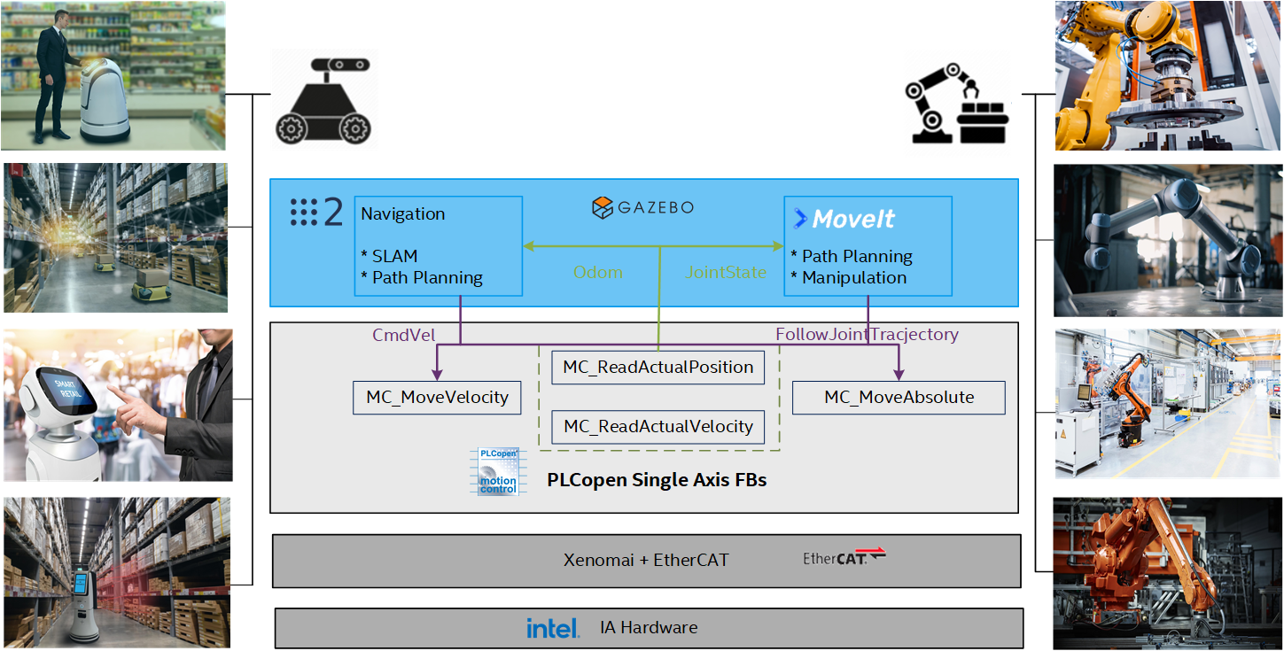
In ECI, the concept has been proven in the joint-lab project between SYMG and Intel through controlling an omni-directional AMR with four servo motors by integrating ROS2 navigation, SoftPLC (commercial and open sourced), PLCopen motion function blocks, and IgH EtherCAT master stack, and running the whole software stack on ECI optimized real-time Linux kernel.
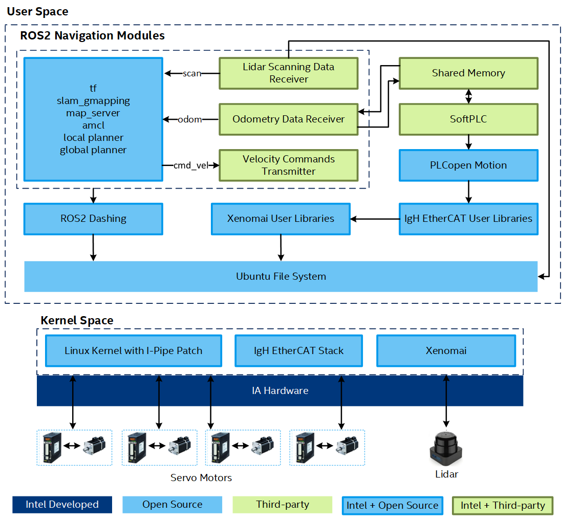
As shown in the above figure, ROS2 navigation plans the global path routine and local trajectory for the AMR to move. When AMR moves, the velocity command cmd_vel, calculated by ROS2 Navigation, is transmitted to the SoftPLC system through the shared memory. This guarantees the efficient communication and good separation between real-time and non real-time processes. The velocity command cmd_vel includes three components indicating the velocities translating forward (VelX), translating sideways (VelY), and rotating round the center of mass (VelRZ) on the 2-D plane. The AMR velocity command is parsed and split into the velocities of four Mecanum 4 wheels (UL, UR, LL, LR). The following figure shows the details of this split process. The velocity command of each wheel is input into a MC_MoveVelocty function block to execute. The MC_MoveVelocity function block makes path interpolation between the velocity inputs and sends the command to the servo motor through the IgH EtherCAT stack. At the same time, the SoftPLC calls the function blocks MC_ReadActualPosition and MC_ReadActualVelocity to read the wheel velocity, and synthesize the information into the odometry of AMR. The odometry information is then transmitted back to ROS2 navigation through the shared memory for the SLAM calculation.

The following is the ST program for this application, which is configured to run in 1ms cycle:
Click to view the ST program
(* Split the AMR velocity into the wheel velocities *)
FUNCTION_BLOCK AGVM_VelCartesian2Wheels
  VAR_INPUT
    VelX :    LREAL;
    VelY :    LREAL;
    VelRZ :   LREAL;
  END_VAR

  VAR_OUTPUT
    UL :      LREAL;
    UR :      LREAL;
    LL :      LREAL;
    LR :      LREAL;
  END_VAR

  VAR_EXTERNAL
    WheelHDistance :  LREAL;(**)
    WheelVDistance :  LREAL;(**)
  END_VAR

  VAR
    VelLZ :   LREAL;
  END_VAR

  VelLZ := VelRZ * ((WheelHDistance + WheelVDistance) / LREAL#2.0);

  UL := VelX - VelY - VelLZ;
  UR := VelX + VelY + VelLZ;
  LL := VelX + VelY - VelLZ;
  LR := VelX - VelY + VelLZ;
END_FUNCTION_BLOCK

(* Synthesize the wheel velocities into the AMR velocity *)
FUNCTION_BLOCK AGVM_VelWheels2Cartesian
  VAR_INPUT
    UL :      LREAL;
    UR :      LREAL;
    LL :      LREAL;
    LR :      LREAL;
  END_VAR

  VAR_OUTPUT
    VelX :    LREAL;
    VelY :    LREAL;
    VelRZ :   LREAL;
  END_VAR

  VAR_EXTERNAL
    WheelHDistance :  LREAL;(**)
    WheelVDistance :  LREAL;(**)
  END_VAR

  VelX := (UL + UR + LL + LR) / LREAL#4.0;

  VelY := (-UL + UR + LL - LR) / LREAL#4.0;
  VelRZ := (-UL + UR - LL + LR) / LREAL#4.0 / ((WheelHDistance + WheelVDistance) / LREAL#2.0);
END_FUNCTION_BLOCK

(* Global variables *)
VAR_GLOBAL
  PLC_SYS_TICK_CNT    AT %MD1.0 :     UDINT;
  PLC_TASK_DEFINED    AT %MW1.4 :     INT;
  PLCMODE_ON  AT %MX1.2016.0 :        BOOL;(*TRUE : current PLC mode is ON*)
  PLCMODE_LOADING     AT %MX1.2017.0 :        BOOL;(*TRUE : current PLC mode is LOADING*)
  PLCMODE_STOP        AT %MX1.6.0 :   BOOL;(*TRUE : current PLC mode is STOP*)
  PLCMODE_RUN AT %MX1.7.0 :   BOOL;(*TRUE : current PLC mode is RUN*)
  PLCMODE_HALT        AT %MX1.8.0 :   BOOL;(*TRUE : current PLC mode is HALT*)
  PLC_TICKS_PER_SEC   AT %MW1.2000 :  UINT;
  PLC_MAX_ERRORS      AT %MD1.2004 :  UDINT;
  PLC_ERRORS  AT %MD1.2008 :  UDINT;
  PLC_TASK_AVAILABLE  AT %MW1.2012 :  INT;
  PLC_SYSTASK_AVAILABLE       AT %MW1.2016 :  INT;
  PLCDEBUG_FORCE      AT %MX1.2018.0 :        BOOL;(*TRUE : current PLC mode is POWER on*)
  PLCDEBUG_BPSET      AT %MX1.2019.0 :        BOOL;(*TRUE : one or more*)
  PLCDEBUG_POWERFLOW  AT %MX1.2020.0 :        BOOL;(*TRUE : current PLC mode is POWER on*)
  WheelVDistance :    LREAL := 0.483;(*Distance between the front and back wheels*)
  WheelHDistance :    LREAL := 0.371;(*Distance between the two side wheels*)
END_VAR

(* Main program *)
PROGRAM main
  VAR
    Acc :     LREAL := 2.0;
    MC_Power_1 :      MC_Power;
    MC_Power_2 :      MC_Power;
    MC_Power_3 :      MC_Power;
    MC_Power_4 :      MC_Power;
    PowStat : BOOL;
    AxisLL :  DINT := 3;
    AxisLR :  DINT := 4;
    AxisUL :  DINT := 1;
    AxisUR :  DINT := 2;
    RatioLimit :      LREAL := 1.0;
    VAxisULVel :      LREAL;
    VAxisURVel :      LREAL;
    VAxisLLVel :      LREAL;
    VAxisLRVel :      LREAL;
    VAxisMaxVel :     LREAL;
    AxisVelLimit :    LREAL := 0.75;
    MC_EmergencyStop_1 :      MC_EmergencyStop;
    MC_Reset_1 :      MC_Reset;
    TransH :  LREAL;
    TransV :  LREAL;
    Twist :   LREAL;
    MC_Reset_2 :      MC_Reset;
    MC_Reset_3 :      MC_Reset;
    MC_Reset_4 :      MC_Reset;
    ENABLE_FLAG :     BOOL;
    MC_Halt_2 :       MC_Halt;
    MC_Halt_3 :       MC_Halt;
    MC_Halt_4 :       MC_Halt;
    MC_MoveVelocity_2 :       MC_MoveVelocity;
    MC_MoveVelocity_3 :       MC_MoveVelocity;
    MC_MoveVelocity_4 :       MC_MoveVelocity;
    MC_Halt_1 :       MC_Halt;
    MC_MoveVelocity_1 :       MC_MoveVelocity;
    SHM_PosX  AT %ML3.200 :   LREAL := 0.0;
    SHM_PosY  AT %ML3.208 :   LREAL := 0.0;
    SHM_PosRZ AT %ML3.216 :   LREAL := 0.0;
    SHM_VelX  AT %ML3.224 :   LREAL := 0.0;
    SHM_VelY  AT %ML3.232 :   LREAL := 0.0;
    SHM_VelRZ AT %ML3.240 :   LREAL := 0.0;
    SHM_Error AT %MX3.248.0 : BOOL;
    MC_ReadAxisError_1 :      MC_ReadAxisError;
    SHM_Enable        AT %MX3.100.0 : BOOL;
    SHM_EmergStop     AT %MX3.101.0 : BOOL;
    SHM_TransH        AT %ML3.102 :   LREAL := 0.0;
    SHM_Twist AT %ML3.118 :   LREAL := 0.0;
    SHM_TransV        AT %ML3.110 :   LREAL := 0.0;
    MC_SetPosition_1 :        MC_SetPosition;
    MC_ReadActualPosition_1 : MC_ReadActualPosition;
    AGVM_VelCartesian2Wheels_1 :      AGVM_VelCartesian2Wheels;
    MC_ReadActualVelocity_1 : MC_ReadActualVelocity;
    MC_ReadActualVelocity_2 : MC_ReadActualVelocity;
    MC_ReadActualVelocity_3 : MC_ReadActualVelocity;
    MC_ReadActualVelocity_4 : MC_ReadActualVelocity;
    AGVM_VelWheels2Cartesian_1 :      AGVM_VelWheels2Cartesian;
    AxisULPos :       LREAL;
    MC_ReadActualPosition_2 : MC_ReadActualPosition;
    MC_ReadActualPosition_3 : MC_ReadActualPosition;
    MC_ReadActualPosition_4 : MC_ReadActualPosition;
    AxisURPos :       LREAL;
    AxisLLPos :       LREAL;
    AxisLRPos :       LREAL;
    AGVM_VelWheels2Cartesian_2 :      AGVM_VelWheels2Cartesian;
    AxisULErr :       WORD;
    AxisURErr :       WORD;
    AxisLLErr :       WORD;
    AxisLRErr :       WORD;
    INIT :    BOOL := TRUE;
    MC_MoveAbsolute_1 :       MC_MoveAbsolute;
  END_VAR

  TransV := SHM_TransV;
  TransH := SHM_TransH;
  Twist := SHM_Twist;

  IF SHM_EmergStop THEN
    SHM_EmergStop := FALSE;
    SHM_Enable := FALSE;
    ENABLE_FLAG:=FALSE;
    MC_EmergencyStop_1(Execute:=FALSE);
    MC_EmergencyStop_1(Axis:=AxisUL,Execute:=TRUE);
    MC_EmergencyStop_1(Execute:=FALSE);
    MC_EmergencyStop_1(Axis:=AxisUR,Execute:=TRUE);
    MC_EmergencyStop_1(Execute:=FALSE);
    MC_EmergencyStop_1(Axis:=AxisLL,Execute:=TRUE);
    MC_EmergencyStop_1(Execute:=FALSE);
    MC_EmergencyStop_1(Axis:=AxisLR,Execute:=TRUE);
  END_IF;

  IF SHM_Enable THEN
    SHM_Enable := FALSE;
    IF NOT PowStat THEN
      MC_Reset_1(Execute:=FALSE);
      MC_Reset_2(Execute:=FALSE);
      MC_Reset_3(Execute:=FALSE);
      MC_Reset_4(Execute:=FALSE);
      ENABLE_FLAG:=TRUE;
    END_IF;
  END_IF;

  IF ENABLE_FLAG THEN
    MC_Reset_1(Axis:=AxisUL,Execute:=TRUE);
    MC_Reset_2(Axis:=AxisUR,Execute:=TRUE);
    MC_Reset_3(Axis:=AxisLL,Execute:=TRUE);
    MC_Reset_4(Axis:=AxisLR,Execute:=TRUE);

    IF MC_Reset_1.Done AND MC_Reset_2.Done AND MC_Reset_3.Done AND MC_Reset_4.Done THEN
      ENABLE_FLAG := FALSE;
    END_IF;
  END_IF;

  MC_Power_1(Axis:=AxisUL,Enable:=TRUE,EnablePositive:=TRUE,EnableNegative:=TRUE);
  MC_Power_2(Axis:=AxisUR,Enable:=TRUE,EnablePositive:=TRUE,EnableNegative:=TRUE);
  MC_Power_3(Axis:=AxisLL,Enable:=TRUE,EnablePositive:=TRUE,EnableNegative:=TRUE);
  MC_Power_4(Axis:=AxisLR,Enable:=TRUE,EnablePositive:=TRUE,EnableNegative:=TRUE);

  PowStat := MC_Power_1.Status AND MC_Power_1.Valid AND
        MC_Power_2.Status AND MC_Power_2.Valid AND
        MC_Power_3.Status AND MC_Power_3.Valid AND
        MC_Power_4.Status AND MC_Power_4.Valid;

  IF PowStat THEN
    IF INIT THEN
      MC_SetPosition_1(Execute:=FALSE);
      MC_SetPosition_1(Axis:=AxisUL,Execute:=TRUE,Position:=LREAL#0.0,Relative:=FALSE,Source:=DINT#1);
      MC_SetPosition_1(Execute:=FALSE);
      MC_SetPosition_1(Axis:=AxisUR,Execute:=TRUE,Position:=LREAL#0.0,Relative:=FALSE,Source:=DINT#1);
      MC_SetPosition_1(Execute:=FALSE);
      MC_SetPosition_1(Axis:=AxisLL,Execute:=TRUE,Position:=LREAL#0.0,Relative:=FALSE,Source:=DINT#1);
      MC_SetPosition_1(Execute:=FALSE);
      MC_SetPosition_1(Axis:=AxisLR,Execute:=TRUE,Position:=LREAL#0.0,Relative:=FALSE,Source:=DINT#1);
      SHM_PosX:=LREAL#0.0;
      SHM_PosY:=LREAL#0.0;
      SHM_PosRZ:=LREAL#0.0;
      AxisULPos:=LREAL#0.0;
      AxisURPos:=LREAL#0.0;
      AxisLLPos:=LREAL#0.0;
      AxisLRPos:=LREAL#0.0;
      INIT:=FALSE;
    END_IF;

    AGVM_VelCartesian2Wheels_1(VelX:=TransV,VelY:=TransH,VelRZ:=Twist);
    VAxisULVel:=AGVM_VelCartesian2Wheels_1.UL;
    VAxisURVel:=AGVM_VelCartesian2Wheels_1.UR;
    VAxisLLVel:=AGVM_VelCartesian2Wheels_1.LL;
    VAxisLRVel:=AGVM_VelCartesian2Wheels_1.LR;

    RatioLimit := LREAL#1.0;
    VAxisMaxVel := ABS(VAxisULVel);

    IF VAxisMaxVel < ABS(VAxisURVel) THEN
      VAxisMaxVel := ABS(VAxisURVel);
    END_IF;

    IF VAxisMaxVel < ABS(VAxisLLVel) THEN
      VAxisMaxVel := ABS(VAxisLLVel);
    END_IF;

    IF VAxisMaxVel < ABS(VAxisLRVel) THEN
      VAxisMaxVel := ABS(VAxisLRVel);
    END_IF;

    IF VAxisMaxVel = LREAL#0.0 THEN
      RatioLimit := LREAL#0.0;
    ELSIF VAxisMaxVel > AxisVelLimit THEN
      RatioLimit := AxisVelLimit / VAxisMaxVel;
    END_IF;

    IF VAxisULVel = LREAL#0.0 THEN
      MC_Halt_1(Execute:=FALSE);
      MC_Halt_1(Axis:=AxisUL,Execute:=TRUE,Deceleration:=Acc);
    ELSE
      MC_MoveVelocity_1(Execute:=FALSE);
      MC_MoveVelocity_1(Axis:=AxisUL,Execute:=TRUE,Velocity:=VAxisULVel * RatioLimit,Acceleration:=Acc,Deceleration:=Acc);
    END_IF;

    IF VAxisURVel = LREAL#0.0 THEN
      MC_Halt_2(Execute:=FALSE);
      MC_Halt_2(Axis:=AxisUR,Execute:=TRUE,Deceleration:=Acc);
    ELSE
      MC_MoveVelocity_2(Execute:=FALSE);
      MC_MoveVelocity_2(Axis:=AxisUR,Execute:=TRUE,Velocity:=VAxisURVel * RatioLimit,Acceleration:=Acc,Deceleration:=Acc);
    END_IF;

    IF VAxisLLVel = LREAL#0.0 THEN
      MC_Halt_3(Execute:=FALSE);
      MC_Halt_3(Axis:=AxisLL,Execute:=TRUE,Deceleration:=Acc);
    ELSE
      MC_MoveVelocity_3(Execute:=FALSE);
      MC_MoveVelocity_3(Axis:=AxisLL,Execute:=TRUE,Velocity:=VAxisLLVel * RatioLimit,Acceleration:=Acc,Deceleration:=Acc);
    END_IF;

    IF VAxisLRVel = LREAL#0.0 THEN
      MC_Halt_4(Execute:=FALSE);
      MC_Halt_4(Axis:=AxisLR,Execute:=TRUE,Deceleration:=Acc);
    ELSE
      MC_MoveVelocity_4(Execute:=FALSE);
      MC_MoveVelocity_4(Axis:=AxisLR,Execute:=TRUE,Velocity:=VAxisLRVel * RatioLimit,Acceleration:=Acc,Deceleration:=Acc);
    END_IF;
  END_IF;

  MC_ReadActualVelocity_1(Axis:=AxisUL,Enable:=TRUE);
  MC_ReadActualVelocity_2(Axis:=AxisUR,Enable:=TRUE);
  MC_ReadActualVelocity_3(Axis:=AxisLL,Enable:=TRUE);
  MC_ReadActualVelocity_4(Axis:=AxisLR,Enable:=TRUE);

  AGVM_VelWheels2Cartesian_1(
    UL:=MC_ReadActualVelocity_1.Velocity,
    UR:=MC_ReadActualVelocity_2.Velocity,
    LL:=MC_ReadActualVelocity_3.Velocity,
    LR:=MC_ReadActualVelocity_4.Velocity);

  SHM_VelX:=AGVM_VelWheels2Cartesian_1.VelX;
  SHM_VelY:=AGVM_VelWheels2Cartesian_1.VelY;
  SHM_VelRZ:=AGVM_VelWheels2Cartesian_1.VelRZ;

  MC_ReadActualPosition_1(Axis:=AxisUL,Enable:=TRUE);
  MC_ReadActualPosition_2(Axis:=AxisUR,Enable:=TRUE);
  MC_ReadActualPosition_3(Axis:=AxisLL,Enable:=TRUE);
  MC_ReadActualPosition_4(Axis:=AxisLR,Enable:=TRUE);

  AGVM_VelWheels2Cartesian_2(
    UL:=MC_ReadActualPosition_1.Position - AxisULPos,
    UR:=MC_ReadActualPosition_2.Position - AxisURPos,
    LL:=MC_ReadActualPosition_3.Position - AxisLLPos,
    LR:=MC_ReadActualPosition_4.Position - AxisLRPos);

  SHM_PosX:=SHM_PosX + (AGVM_VelWheels2Cartesian_2.VelX * COS(SHM_PosRZ) - AGVM_VelWheels2Cartesian_2.VelY * SIN(SHM_PosRZ));
  SHM_PosY:=SHM_PosY + (AGVM_VelWheels2Cartesian_2.VelX * SIN(SHM_PosRZ) + AGVM_VelWheels2Cartesian_2.VelY * COS(SHM_PosRZ));
  SHM_PosRZ:=SHM_PosRZ + AGVM_VelWheels2Cartesian_2.VelRZ;

  AxisULPos:=MC_ReadActualPosition_1.Position;
  AxisURPos:=MC_ReadActualPosition_2.Position;
  AxisLLPos:=MC_ReadActualPosition_3.Position;
  AxisLRPos:=MC_ReadActualPosition_4.Position;

  MC_ReadAxisError_1(Axis:=AxisUL,Enable:=TRUE);
  AxisULErr:=MC_ReadAxisError_1.ErrorID;

  MC_ReadAxisError_1(Axis:=AxisUR,Enable:=TRUE);
  AxisURErr:=MC_ReadAxisError_1.ErrorID;

  MC_ReadAxisError_1(Axis:=AxisLL,Enable:=TRUE);
  AxisLLErr:=MC_ReadAxisError_1.ErrorID;

  MC_ReadAxisError_1(Axis:=AxisLR,Enable:=TRUE);
  AxisLRErr:=MC_ReadAxisError_1.ErrorID;
END_PROGRAM
S-curve Trajectory Planning
S-curve trajectory planning is the core function of the PLCopen function blocks for single axis motion control. When driving a motor to an absolute or additive position, the motors always try to accelerate its velocity to its maximum value and decelerate before it reaches the target position. If the acceleration during this process is not continuous or linear piece-wise, some infinite jerk spikes may happen. For this reason, this trajectory may generate efforts and stresses on the mechanical system of motors that may result detrimental or generate undesired vibrational effects. Therefore, the S-curve trajectory planning is necessary.
A sample implementation of the S-curve algorithm is provided in ECI for reference design. For more information of S-curve planning, refer to “Trajectory Planning for Automatic Machines and Robots-Springer (2008)” by Luigi Biagiotti, Claudio Melchiorri.
PLCopen Motion Sanity Check
Terminology in the following sections:
Term |
Description |
|---|---|
S0 |
Start position |
S1 |
End position |
V0 |
Start velocity |
V1 |
End velocity |
A0 |
Start acceleration |
A1 |
End acceleration |
Vmin |
Minimum velocity |
Vmax |
Maximum velocity |
Amin |
Minimum acceleration |
Amax |
Maximum acceleration |
Jmin |
Minimum jerk |
Jmax |
Maximum jerk |
The following section is applicable to:

Sanity Check #1: On-line S-Curve Algorithm Test
$ /opt/plcopen/online_scurve_test
Expected Output
[==========] Running 9 tests from 1 test suite.
[----------] Global test environment set-up.
[----------] 9 tests from ScurveTest
[ RUN      ] ScurveTest.Test1
Polynomial coeffs: a0 43.333340, a0 10.000000, a0 0.000000, a0 -5.625028, a0 2.109407, a0 -0.000009
Scurve profile: Tj2a 0.333333, Tj2b 0.333333, Td 1.333333
Scurve termination: sk_e -0.000000, vk_e 0.000002, ak_e -0.011247
[       OK ] ScurveTest.Test1 (1 ms)
[ RUN      ] ScurveTest.Test2
Polynomial coeffs: a0 0.819853, a0 3.933340, a0 5.000000, a0 -5.265315, a0 -0.676768, a0 1.109904
Scurve profile: Tj2a 0.666667, Tj2b 0.333333, Td 1.226667
Scurve termination: sk_e -0.000000, vk_e 0.000011, ak_e -0.032459
[       OK ] ScurveTest.Test2 (0 ms)
[ RUN      ] ScurveTest.Test3
Polynomial coeffs: a0 0.503677, a0 5.432135, a0 2.955000, a0 -7.379425, a0 3.228023, a0 0.143848
Scurve profile: Tj2a 0.530333, Tj2b 0.500000, Td 1.040094
Scurve termination: sk_e -0.000281, vk_e -0.000468, ak_e -0.004274
[       OK ] ScurveTest.Test3 (0 ms)
[ RUN      ] ScurveTest.Test4
Polynomial coeffs: a0 1.538060, a0 5.233840, a0 2.740000, a0 -1.969392, a0 -10.467462, a0 9.302328
Scurve profile: Tj2a 0.488227, Tj2b 0.238894, Td 0.727121
Scurve termination: sk_e -0.000362, vk_e -0.000241, ak_e -0.012134
[       OK ] ScurveTest.Test4 (0 ms)
[ RUN      ] ScurveTest.Test5
Polynomial coeffs: a0 43.090361, a0 9.993340, a0 0.000000, a0 -6.850631, a0 3.713191, a0 -0.260350
Scurve profile: Tj2a 0.333333, Tj2b 0.400000, Td 1.106001
Scurve termination: sk_e -0.000002, vk_e -0.000001, ak_e -0.000026
[       OK ] ScurveTest.Test5 (0 ms)
[ RUN      ] ScurveTest.Test6
Polynomial coeffs: a0 31.188293, a0 9.993340, a0 0.000000, a0 5.528178, a0 -1.977616, a0 -0.042063
Scurve profile: Tj2a 0.333333, Tj2b 0.266667, Td 1.273999
Scurve termination: sk_e -0.019986, vk_e -0.002014, ak_e 0.031347
[       OK ] ScurveTest.Test6 (0 ms)
[ RUN      ] ScurveTest.Test7
Polynomial coeffs: a0 1.532744, a0 14.421760, a0 -3.560000, a0 5.345304, a0 0.326130, a0 -1.078490
Scurve profile: Tj2a 0.570667, Tj2b 0.266667, Td 1.152981
Scurve termination: sk_e -0.019626, vk_e -0.001984, ak_e 0.044019
[       OK ] ScurveTest.Test7 (0 ms)
[ RUN      ] ScurveTest.Test8
Polynomial coeffs: a0 2.742635, a0 1.570000, a0 0.000000, a0 -6.130163, a0 6.063986, a0 -0.011689
Scurve profile: Tj2a 0.006280, Tj2b 0.006280, Td 0.506280
Scurve termination: sk_e -0.000000, vk_e 0.000001, ak_e -0.010276
[       OK ] ScurveTest.Test8 (0 ms)
[ RUN      ] ScurveTest.Test9
Polynomial coeffs: a0 2.443341, a0 6.753340, a0 5.000000, a0 -5.738710, a0 0.443898, a0 0.434246
Scurve profile: Tj2a 0.666667, Tj2b 0.333333, Td 1.508667
Scurve termination: sk_e -0.000000, vk_e 0.000009, ak_e -0.027303
[       OK ] ScurveTest.Test9 (0 ms)
[----------] 9 tests from ScurveTest (4 ms total)

[----------] Global test environment tear-down
[==========] 9 tests from 1 test suite ran. (4 ms total)
[  PASSED  ] 9 tests.
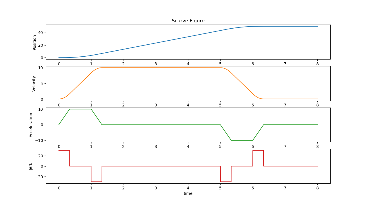
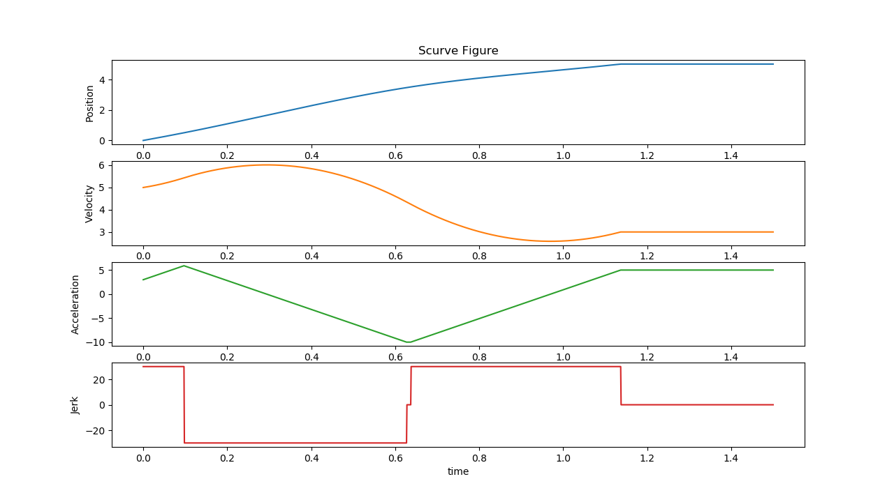
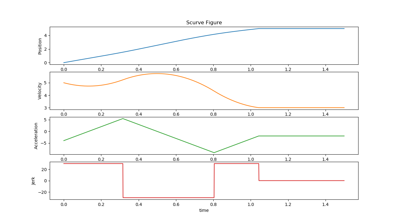
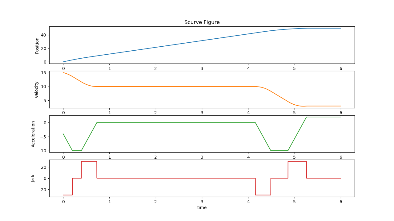
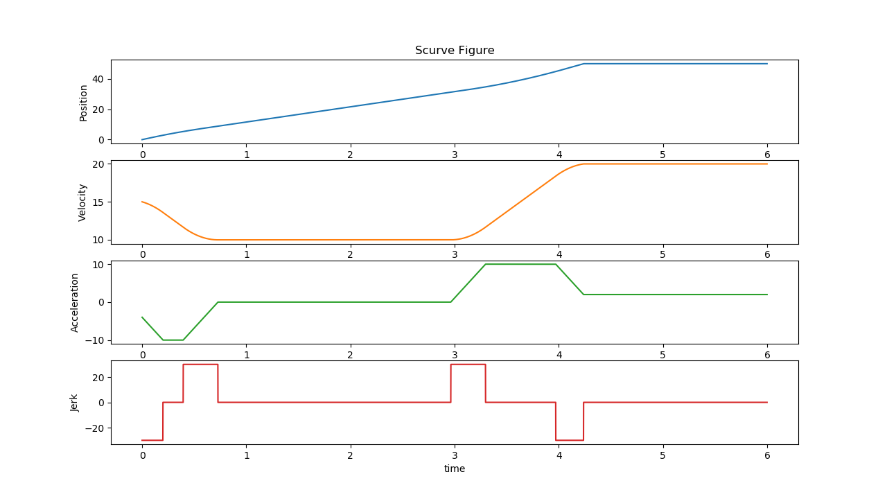
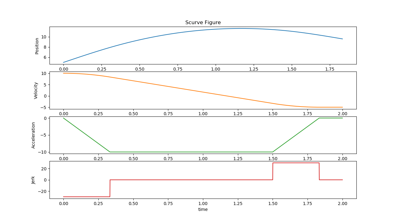
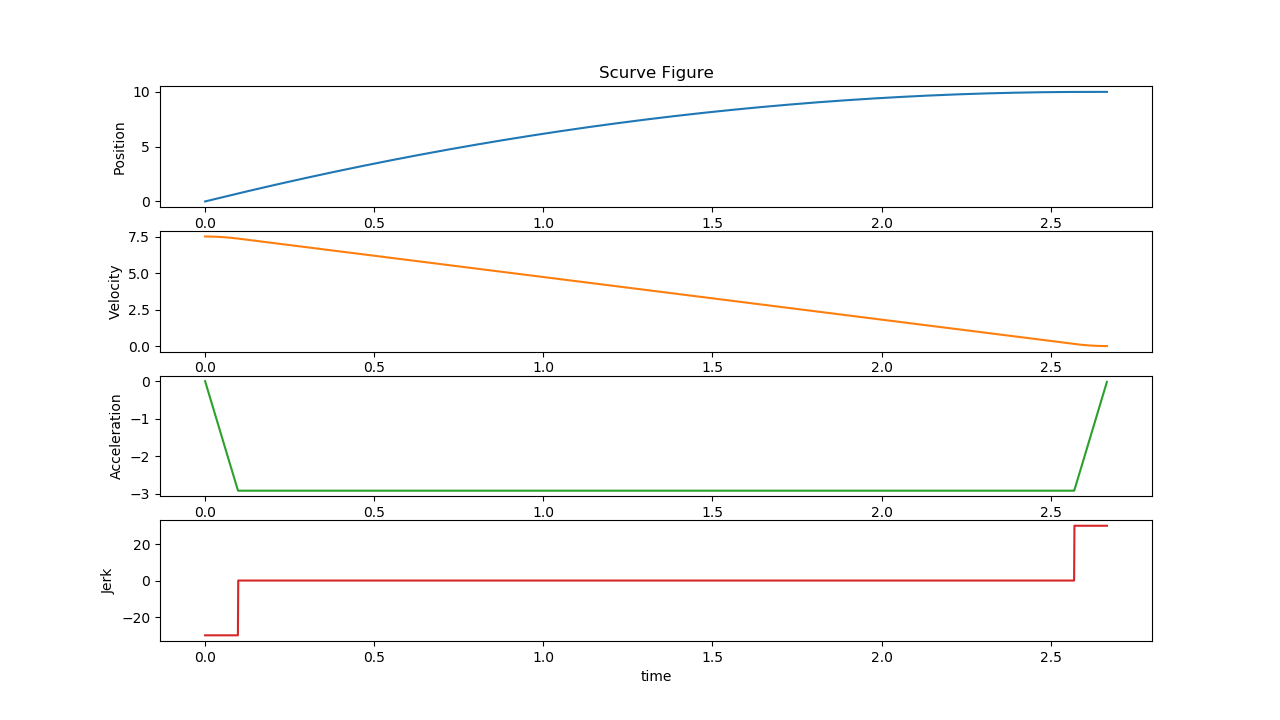
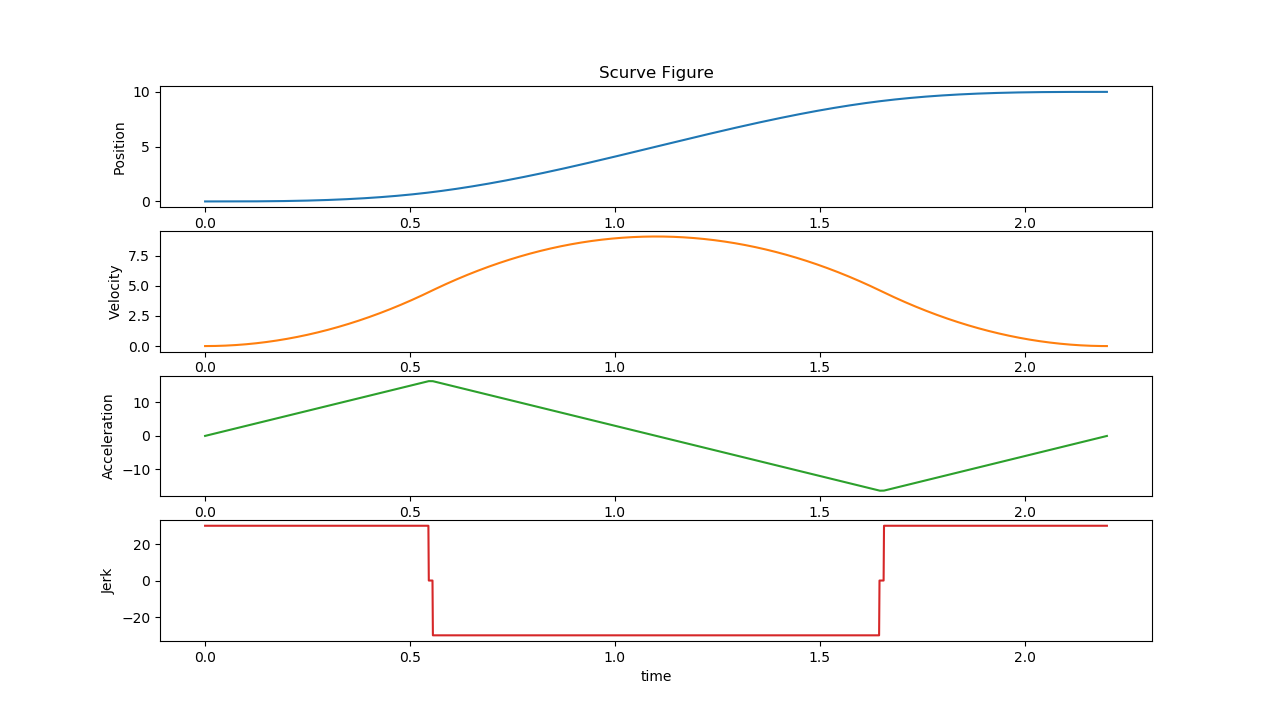
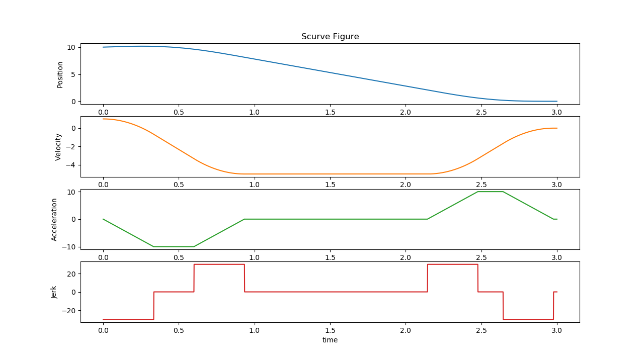
The tests verify the motor trajectory planning under different conditions:
Test1
Input:
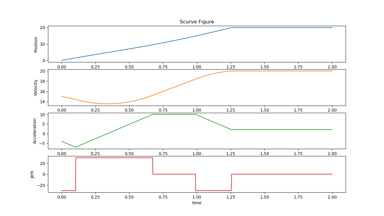
S0: 0, S1: 50, V0: 0, V1: 0, A0: 0, A1: 0Constraints:
Vmin: -10, Vmax: 10, Amin: -10, Amax: 10, Jmin: -30, Jmax: 30Click to view the graph for Test1
Test2
Input:
S0: 0, S1: 5, V0: 0, V1: 0, A0: 0, A1: 0Constraints:
Vmin: -10, Vmax: 10, Amin: -10, Amax: 10, Jmin: -30, Jmax: 30Click to view the graph for Test2
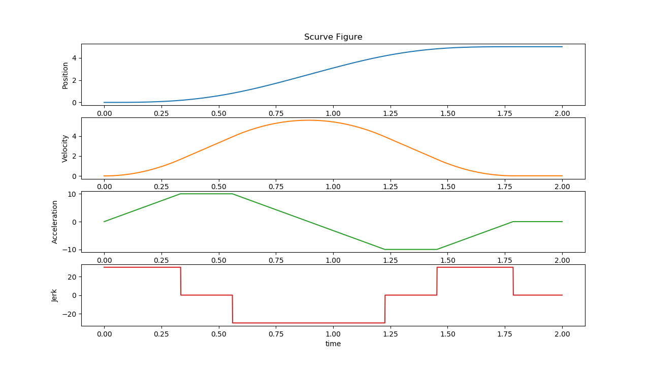
Test3
Input:
S0: 0, S1: 5, V0: 5, V1: 3, A0: 3, A1: 5Constraints:
Vmin: -10, Vmax: 10, Amin: -10, Amax: 10, Jmin: -30, Jmax: 30Click to view the graph for Test3
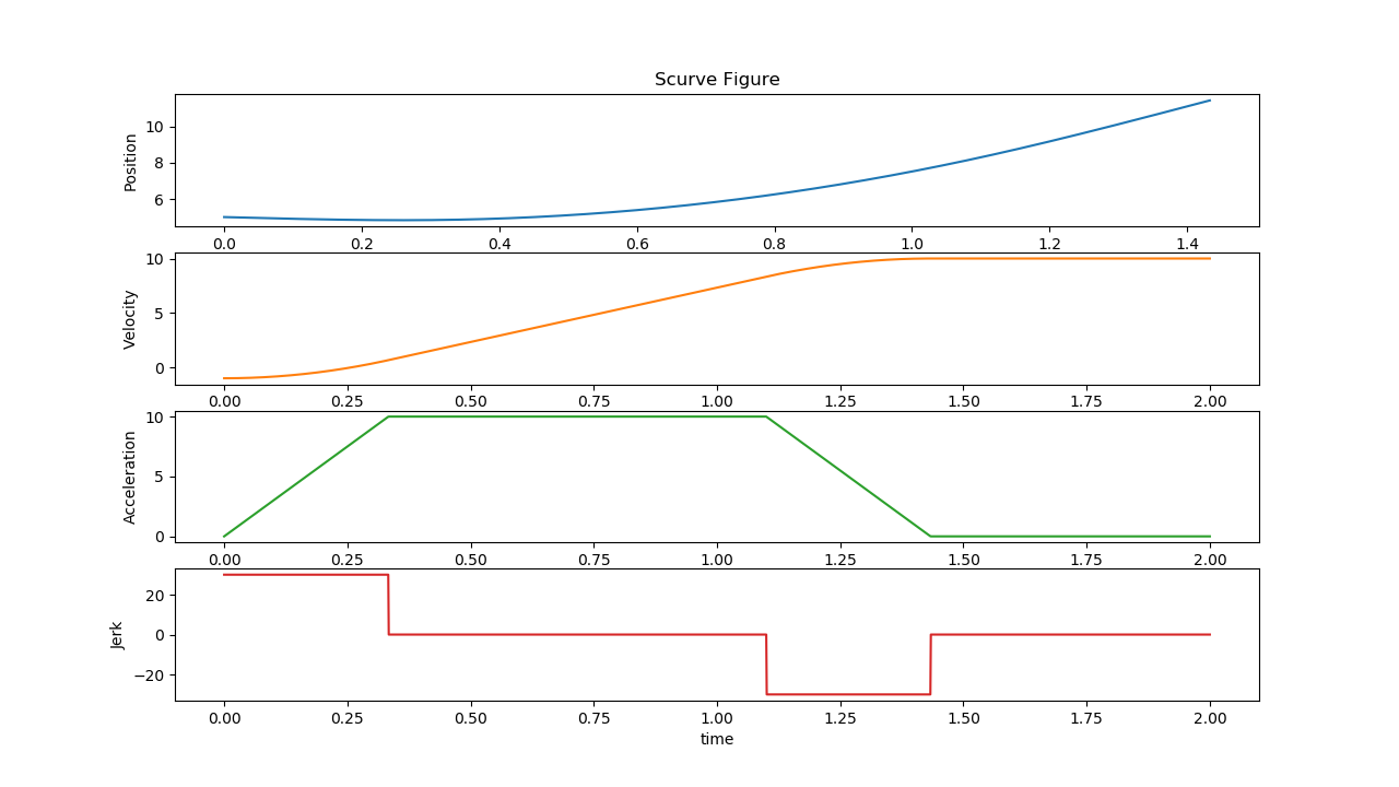
Test4
Input:
S0: 0, S1: 5, V0: 5, V1: 3, A0: -4, A1: 2Constraints:
Vmin: -10, Vmax: 10, Amin: -10, Amax: 10, Jmin: -30, Jmax: 30Click to view the graph for Test4
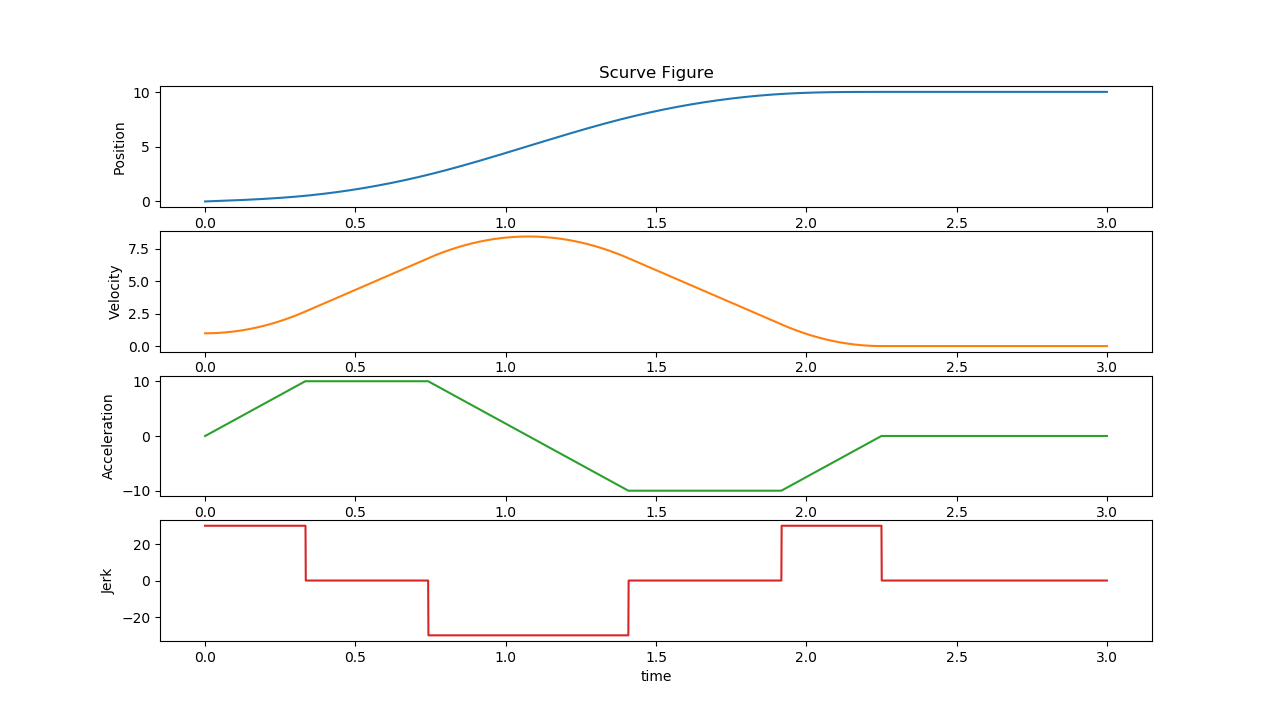
Test5
Input:
S0: 0, S1: 50, V0: 15, V1: 3, A0: -4, A1: 2Constraints:
Vmin: -10, Vmax: 10, Amin: -10, Amax: 10, Jmin: -30, Jmax: 30Click to view the graph for Test5
Test6
Input:
S0: 0, S1: 50, V0: 15, V1: 20, A0: -4, A1: 2Constraints:
Vmin: -10, Vmax: 10, Amin: -10, Amax: 10, Jmin: -30, Jmax: 30Click to view the graph for Test6
Test7
Input:
S0: 0, S1: 20, V0: 15, V1: 20, A0: -4, A1: 2Constraints:
Vmin: -10, Vmax: 10, Amin: -10, Amax: 10, Jmin: -30, Jmax: 30Click to view the graph for Test7
Test8
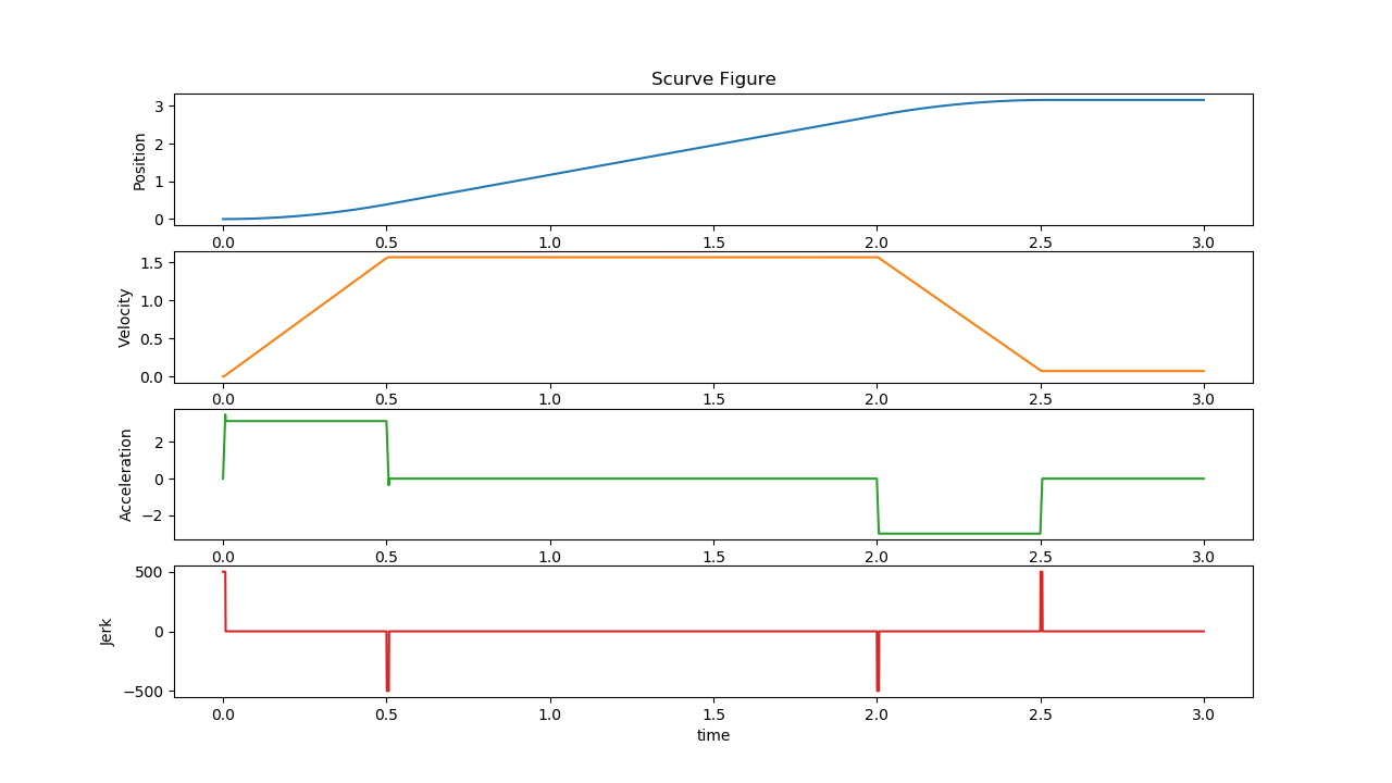
Input:
S0: 0, S1: 3.14, V0: 0, V1: 0, A0: 0, A1: 0Constraints:
Vmin: -1.57, Vmax: 1.57, Amin: -3.14, Amax: 3.14, Jmin: -500, Jmax: 500Click to view the graph for Test8
Test9
Input:
S0: 0, S1: 10, V0: 1, V1: 0, A0: 0, A1: 0Constraints:
Vmin: -10, Vmax: 10, Amin: -10, Amax: 10, Jmin: -30, Jmax: 30Click to view the graph for Test9
The following section is applicable to:
Sanity Check #2: Trajectory Planner Test
$ /opt/plcopen/planner_test
Expected Output
[==========] Running 8 tests from 1 test suite.
[----------] Global test environment set-up.
[----------] 8 tests from PlannerTest
[ RUN      ] PlannerTest.VelocityUp
Scurve profile: Ta = 1.433333, Tv = 0.000000, Td = 0.000000, Tj1 = 0.333333, Tj2 = 0.000000
[       OK ] PlannerTest.VelocityUp (0 ms)
[ RUN      ] PlannerTest.VelocityDown
Scurve profile: Ta = 1.833333, Tv = 0.000000, Td = 0.000000, Tj1 = 0.333333, Tj2 = 0.000000
[       OK ] PlannerTest.VelocityDown (0 ms)
[ RUN      ] PlannerTest.Example_3_9
[       OK ] PlannerTest.Example_3_9 (0 ms)
[ RUN      ] PlannerTest.Example_3_10
[       OK ] PlannerTest.Example_3_10 (0 ms)
[ RUN      ] PlannerTest.Example_3_11
[       OK ] PlannerTest.Example_3_11 (0 ms)
[ RUN      ] PlannerTest.Example_3_12
[       OK ] PlannerTest.Example_3_12 (0 ms)
[ RUN      ] PlannerTest.Example_3_13
[       OK ] PlannerTest.Example_3_13 (0 ms)
[ RUN      ] PlannerTest.Test_Negative
[       OK ] PlannerTest.Test_Negative (0 ms)
[----------] 8 tests from PlannerTest (5 ms total)

[----------] Global test environment tear-down
[==========] 8 tests from 1 test suite ran. (5 ms total)
[  PASSED  ] 8 tests.
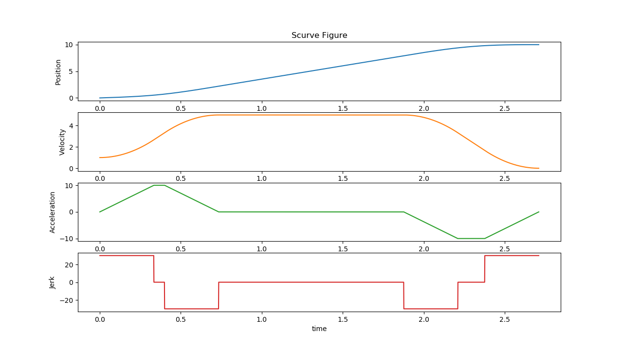
The tests verify the motor trajectory planning under different conditions:
VelocityUp
Input:
S0 5, V0: -1, V1: 10Constraints:
Vmax: 5, Amax 10, Jmax: 30Click to view the graph for VelocityUp
VelocityDown
Input:
S0 5, V0: 10, V1: -5Constraints:
Vmax: 5, Amax 10, Jmax: 30Click to view the graph for VelocityDown
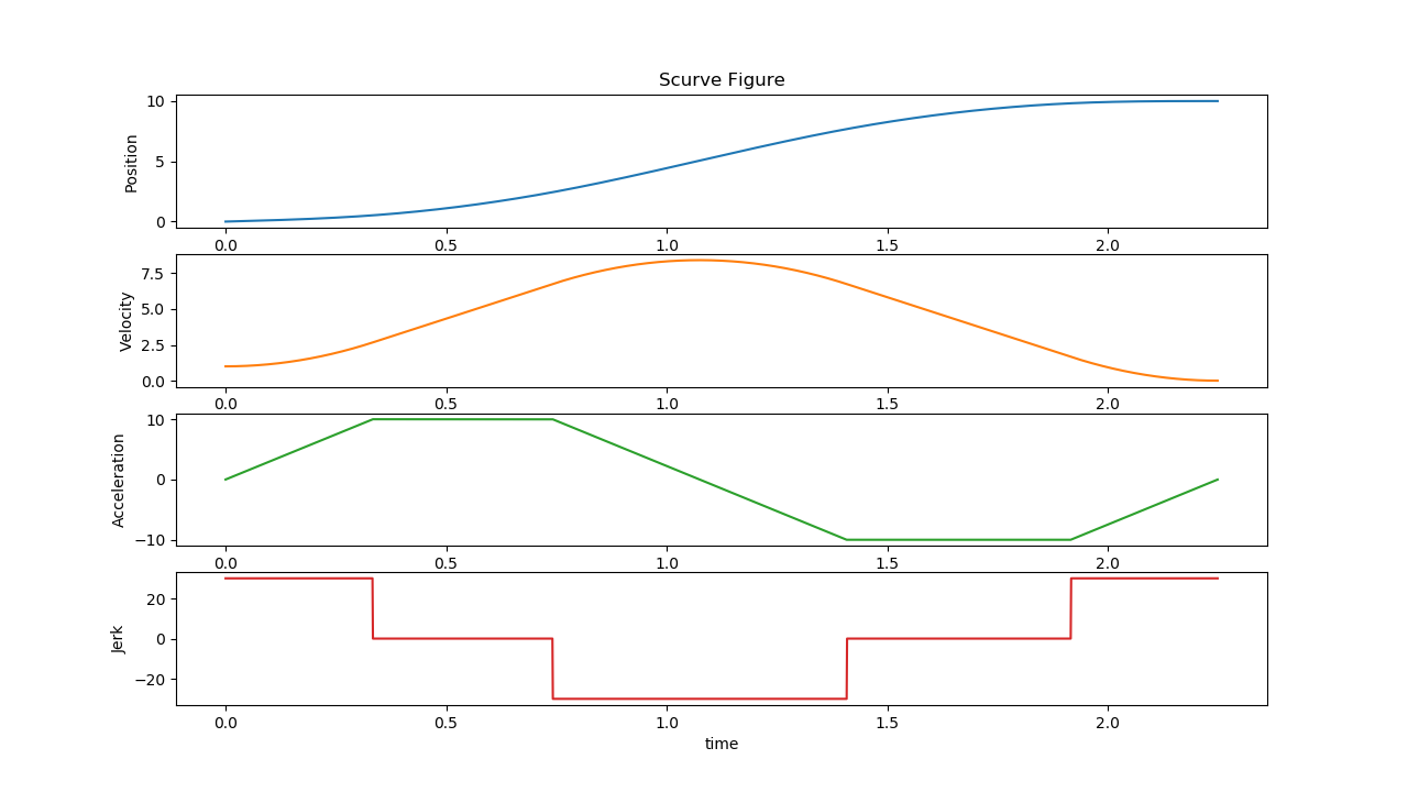
Example_3_9
Input:
S0 0, S1: 10, V0: 1, V1: 0Constraints:
Vmax: 5, Amax 10, Jmax: 30Click to view the graph for Example_3_9
Example_3_10
Input:
S0 0, S1: 10, V0: 1, V1: 0Constraints:
Vmax: 10, Amax 10, Jmax: 30Click to view the graph for Example_3_10
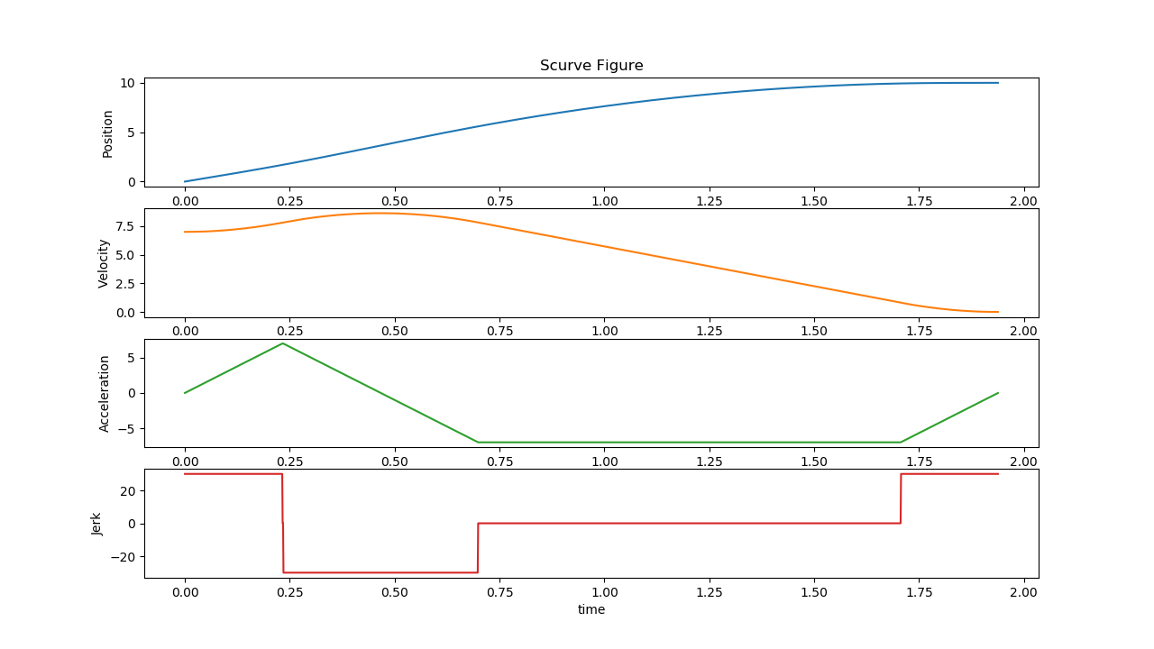
Example_3_11
Input:
S0 0, S1: 10, V0: 7, V1: 0Constraints:
Vmax: 10, Amax 10, Jmax: 30Click to view the graph for Example_3_11
Example_3_12
Input:
S0 0, S1: 10, V0: 7.5, V1: 0Constraints:
Vmax: 10, Amax 10, Jmax: 30Click to view the graph for Example_3_12
Example_3_13
Input:
S0 0, S1: 10, V0: 0, V1: 0Constraints:
Vmax: 10, Amax 20, Jmax: 30Click to view the graph for Example_3_13
Test_Negative
Input:
S0 10, S1: 0, V0: 1, V1: 0Constraints:
Vmax: 5, Amax 10, Jmax: 30Click to view the graph for Test_Negative
The following section is applicable to:
Sanity Check #3: Function Block Test
$ /opt/plcopen/function_block_test
Expected Output
[==========] Running 8 tests from 1 test suite.
[----------] Global test environment set-up.
[----------] 8 tests from FunctionBlockTest
[ RUN      ] FunctionBlockTest.DemoRelative
Axis initialized.
Function block initialized.
Axis #1 powered on, axis_pos_ = 0.000000
FB test end. Delete axis and servo.
[       OK ] FunctionBlockTest.DemoRelative (2545 ms)
[ RUN      ] FunctionBlockTest.DemoVelocity
Axis initialized.
Function block initialized.
Axis #1 powered on, axis_pos_ = 0.000000
FB test end. Delete axis and servo.
[       OK ] FunctionBlockTest.DemoVelocity (565 ms)
[ RUN      ] FunctionBlockTest.MC_Stop
Axis initialized.
axis poweron, moveVel start
Axis #1 powered on, axis_pos_ = 0.000000
FB test end. Delete axis and servo.
[       OK ] FunctionBlockTest.MC_Stop (25000 ms)
[ RUN      ] FunctionBlockTest.MC_Halt
Axis initialized.
axis poweron, moveVel start
Axis #1 powered on, axis_pos_ = 0.000000
FB test end. Delete axis and servo.
[       OK ] FunctionBlockTest.MC_Halt (40000 ms)
[ RUN      ] FunctionBlockTest.MC_MoveAbsolute
Axis initialized.
axis poweron, moveVel start
Axis #1 powered on, axis_pos_ = 0.000000
FB test end. Delete axis and servo.
[       OK ] FunctionBlockTest.MC_MoveAbsolute (7000 ms)
[ RUN      ] FunctionBlockTest.MC_MoveRelative
Axis initialized.
axis poweron, moveVel start
Axis #1 powered on, axis_pos_ = 0.000000
FB test end. Delete axis and servo.
[       OK ] FunctionBlockTest.MC_MoveRelative (4000 ms)
[ RUN      ] FunctionBlockTest.MC_MoveAdditive
Axis initialized.
axis poweron, moveVel start
Axis #1 powered on, axis_pos_ = 0.000000
FB test end. Delete axis and servo.
[       OK ] FunctionBlockTest.MC_MoveAdditive (7000 ms)
[ RUN      ] FunctionBlockTest.MC_MoveVelocity
Axis initialized.
axis poweron, moveVel start
Axis #1 powered on, axis_pos_ = 0.000000
FB test end. Delete axis and servo.
[       OK ] FunctionBlockTest.MC_MoveVelocity (9000 ms)
[----------] 8 tests from FunctionBlockTest (95111 ms total)

[----------] Global test environment tear-down
[==========] 8 tests from 1 test suite ran. (95111 ms total)
[  PASSED  ] 8 tests.
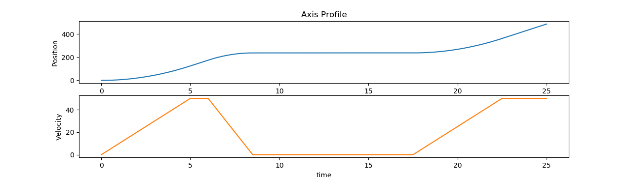
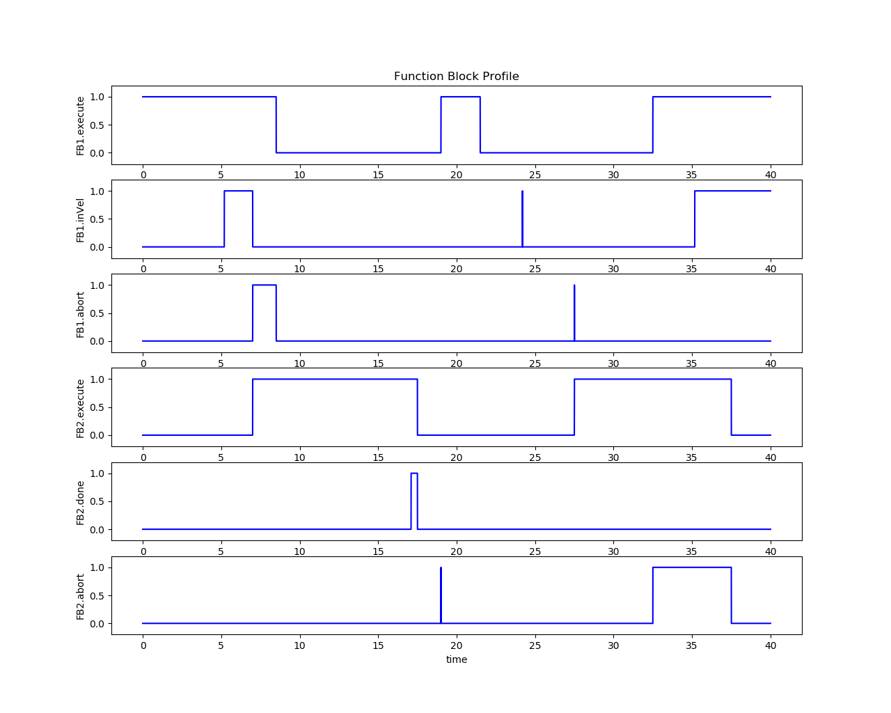
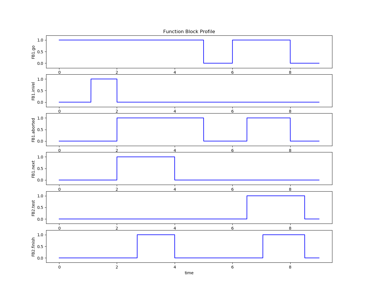
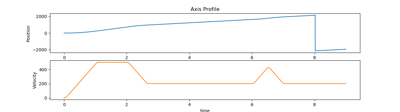
The tests verify the function block execution result and its timing diagram:
MC_Stop
Click to view the graph for MC_Stop
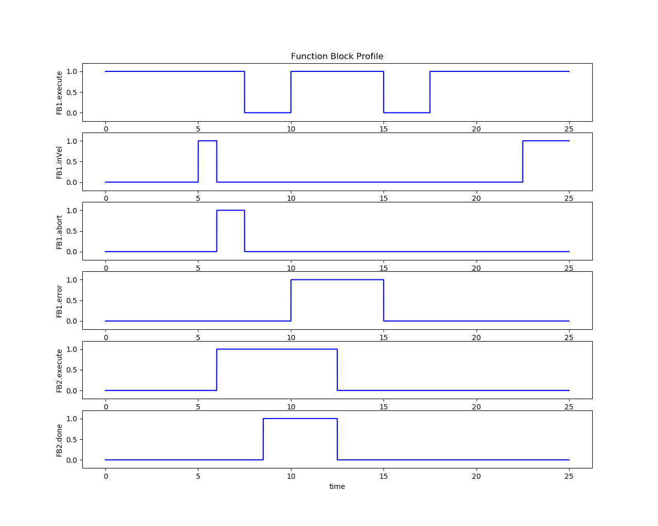
MC_Halt
Click to view the graph for MC_Halt
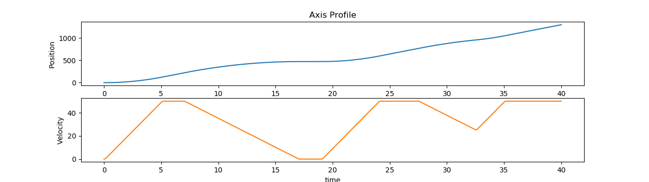
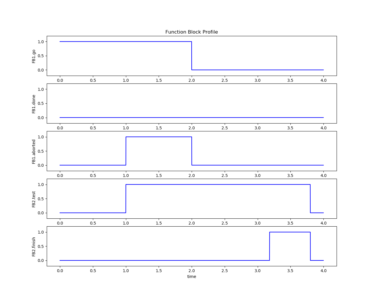
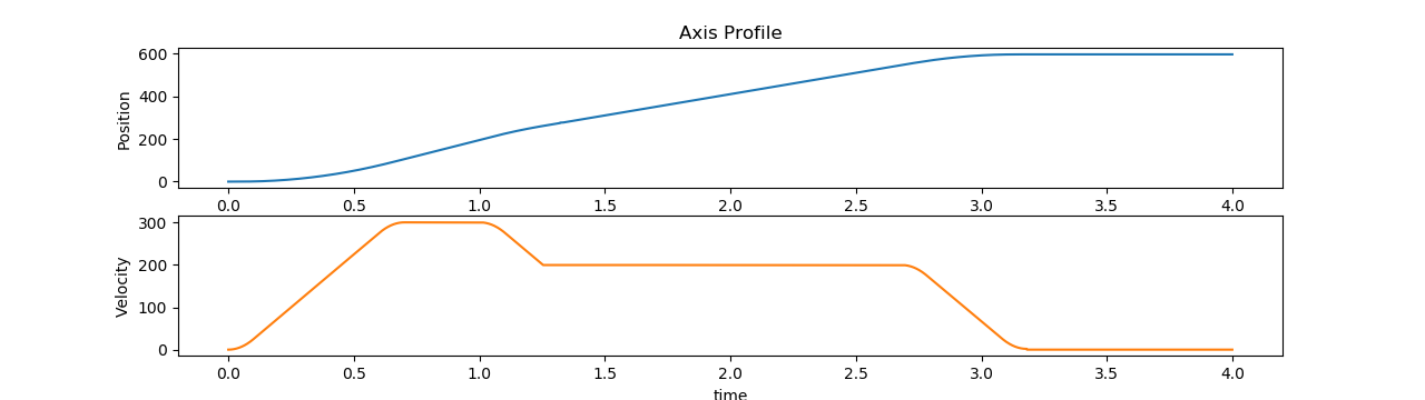
MC_MoveAbsolute
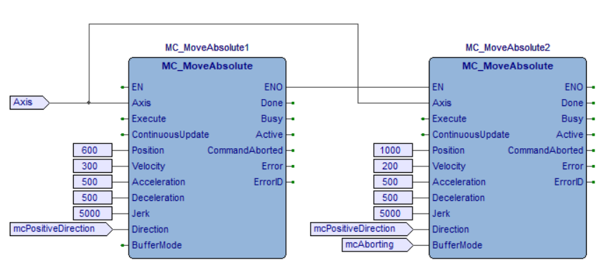
Click to view the graph for MC_MoveAbsolute

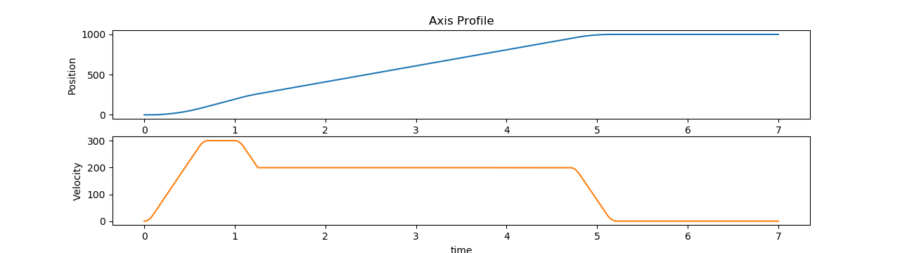
MC_MoveRelative
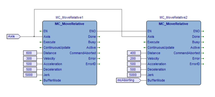
Click to view the graph for MC_MoveRelative
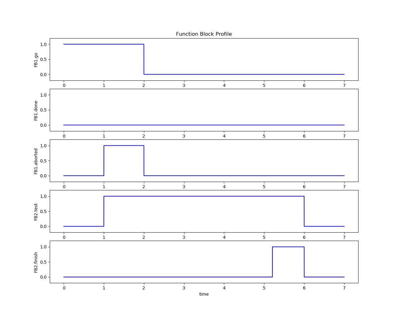
MC_MoveAdditive
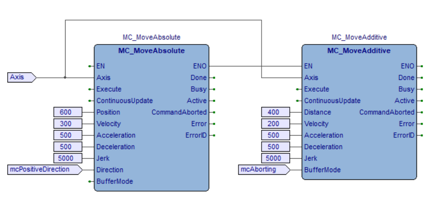
Click to view the graph for MC_MoveAdditive

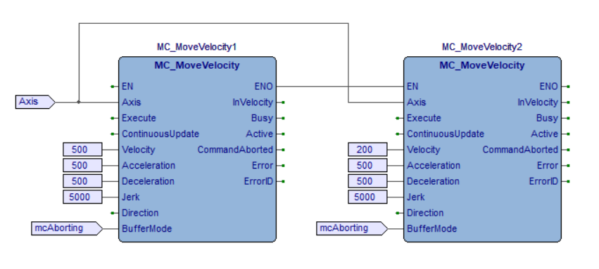
MC_MoveVelocity
Click to view the graph for MC_MoveVelocity
PLCopen Motion Recurring Testing
The following section is applicable to:
Recurring Test #1: Latency and Jitter Benchmarking
This test will repeat running a MC_MoveRelative function block in 1ms real-time cycle. After the function block runs for a while, press crtl+c to stop the program. Performance data will show up, which depends on the chosen hardware and configurations.
$ sudo /opt/plcopen/multi-axis-monitor
Expected Output
starting threading
Axis initialized.
Function block initialized.
Axis #1 powered on, axis_pos_ = 0.000000
time:                0
[CYCLE]   min:  1000.000    max: -1000.000
[JITTER]  min:  1000.000    max: -1000.000
time:                1
[CYCLE]   min:     0.473    max:    13.718
[JITTER]  min:     2.747    max:     5.830
time:                2
[CYCLE]   min:     0.468    max:    13.718
[JITTER]  min:     2.726    max:     6.889
time:                3
[CYCLE]   min:     0.451    max:    13.718
[JITTER]  min:     2.671    max:     7.403
time:                4
[CYCLE]   min:     0.451    max:    13.718
[JITTER]  min:     2.633    max:     7.403
time:                5
[CYCLE]   min:     0.400    max:    13.718
[JITTER]  min:     2.633    max:     7.403
time:                6
[CYCLE]   min:     0.400    max:    13.718
[JITTER]  min:     2.597    max:     7.403
time:                7
[CYCLE]   min:     0.400    max:    13.718
[JITTER]  min:     2.597    max:     7.403
time:                8
[CYCLE]   min:     0.400    max:    13.718
[JITTER]  min:     2.597    max:     7.403
time:                9
[CYCLE]   min:     0.400    max:    13.718
[JITTER]  min:     2.597    max:     7.403
time:               10
[CYCLE]   min:     0.400    max:    13.718
[JITTER]  min:     2.597    max:     7.403
time:               11
[CYCLE]   min:     0.400    max:    13.718
[JITTER]  min:     2.597    max:     7.403
^C*********************************************
average cycle time       0.531
cycle counter            11091
cycle time               0.400 ...     13.718
jitter time              2.597 ...      7.403
*********************************************
- 1
https://www.canadianpackaging.com/automation/introducing-the-alpha-hsm-160845/
- 2(1,2)
https://plcopen.org/downloads/application-examples-plcopen-motion-control
- 3
- 4