PLCopen Motion Control
The PLCopen motion standard provides a way to have standard application libraries that are reusable for multiple hardware platforms. It is widely accepted in the industrial control market for the CNC, robotics and motion control applications. For more detailed information of the PLCopen motion specifications, please refer to https://plcopen.org/technical-activities/motion-control.
![]()
PLCopen Motion Function blocks
In ECI, the PLCopen motion control library Uranus is used with the IgH EtherCAT master stack and SoftPLC to create general motion control applications. Uranus is an open source C++ library delivered by Shenyang Machine Tool (Group) Co.,Ltd (SYMG) in the joint-lab project with Intel. Uranus implements the part 1 & 2 of PLCopen motion control standard. With specially designed extensions to the ROS2 Navigation, Uranus function blocks have been successfully deployed to the control of an Autonomous Mobile Robot (AMR) with four servo motors.
Uranus currently contains these function blocks:
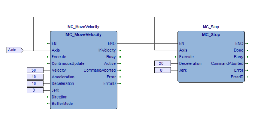
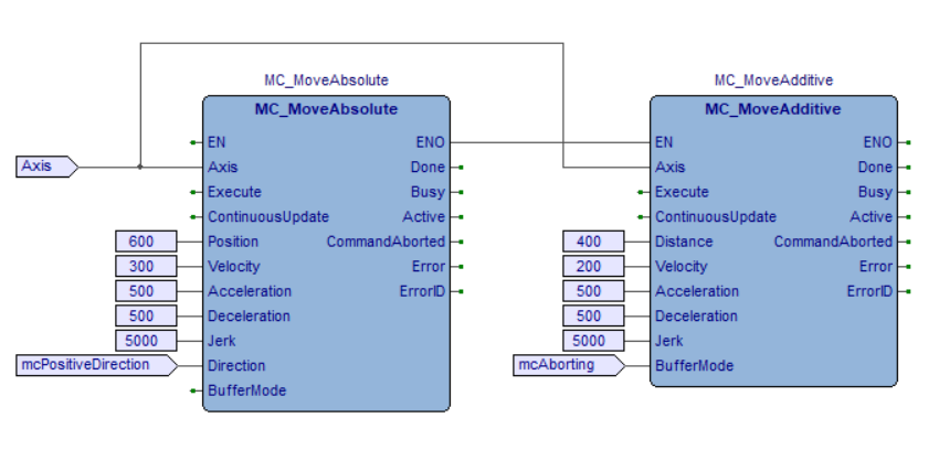
MC_Power: Controls the power stage (On or Off).MC_Home: Commands the axis to perform the «search home» sequence.MC_Stop: Commands a controlled motion stop and transfers the axis to the stateStopping.MC_Halt: Commands a controlled motion stop and transfers the axis to the stateStandStill.MC_MoveAbsolute: Commands a controlled motion to a specified absolute position.MC_MoveRelative: Commands a controlled motion of a specified distance relative to the set position at the time of the execution.MC_MoveAdditive: Commands a controlled motion of a specified relative distance additional to the most recent commanded position.MC_MoveVelocity: Commands a never ending controlled motion at a specified velocity.MC_ReadStatus: Returns in detail the status of the state diagram of the selected axis.MC_ReadMotionState: Returns in detail the status of the axis with respect to the motion currently in progress.MC_ReadAxisError: Reads information concerning an axis, like modes, inputs directly related to the axis, and certain status information.MC_EmergencyStop: Commands the axis to stop immediately and transfers the axis to the stateErrorStop.MC_Reset: Makes the transition from the stateErrorStoptoStandstillorDisabledby resetting all internal axis-related errors.MC_ReadActualPosition: Returns the actual position.MC_ReadCommandPosition: Returns the command position.MC_ReadActualVelocity: Returns the actual velocity.MC_ReadCommandVelocity: Returns the command velocity.
Install Uranus:
$ cd ${uranus_root}
$ mkdir build && cd build && cmake ..
$ make
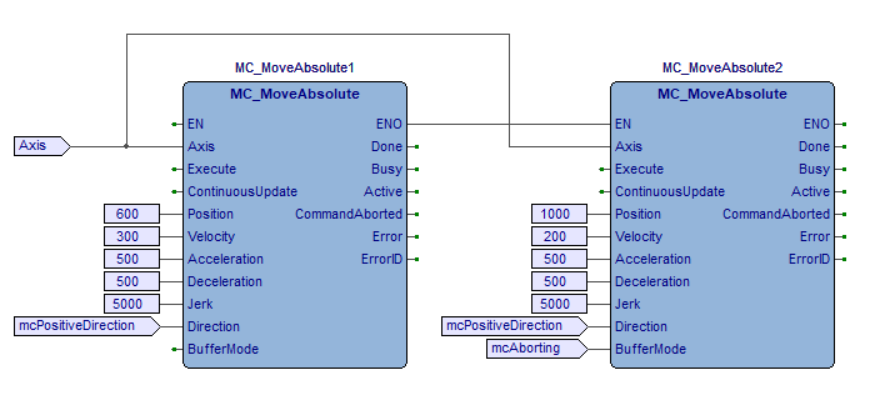
Run axis_move demo to execute two MC_MoveAbsolute function blocks in sequence:
$ cd ${uranus_root}/build
$ ./axis_move
The following sections will show detailed instructions on how to use Uranus function blocks to develop motion control applications for industrial automation and robotics.
Applications for Industrial Automation
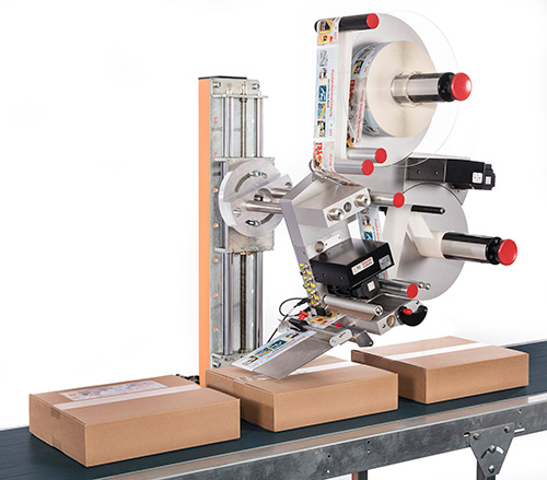
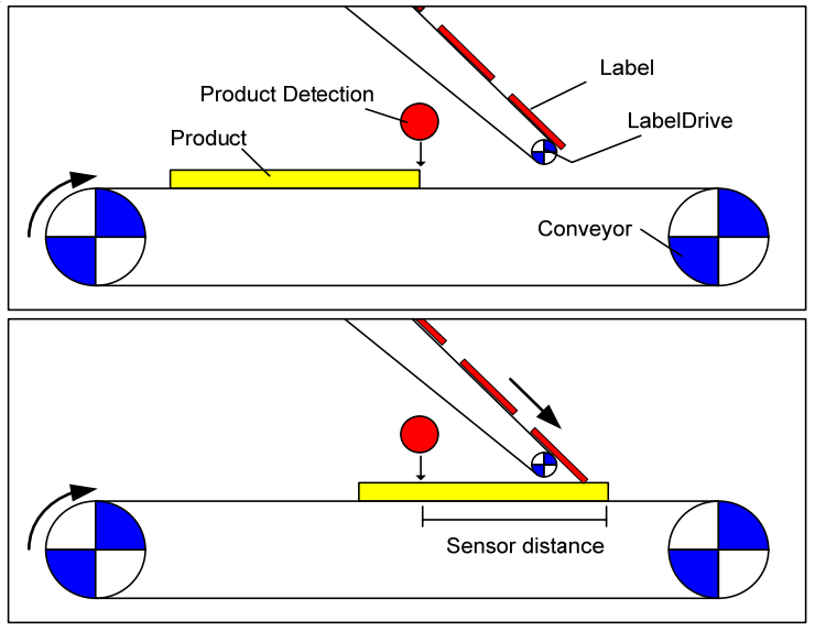
Labeling is commonly seen in the automation of the pharmaceuticals, beverage, and chemicals packaging. As shown in the figures below(left 1 and right 2), the task is to place a label at a particular position on a product. The application has two drives, one to feed the product via a conveyor belt, the other to feed the labels and to place the labels on the products. The labeling process is triggered by a position detection sensor. From the detection of the product to the start of the label movement there is a delay depending on the velocity of the conveyor, the position of the sensor and the position of the label on the product.
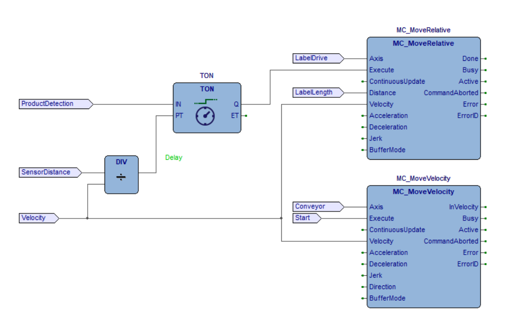
Uranus motion control function blocks can be used with the SoftPLC systems, e.g. Codesys, MULTIPROG and LogicLab, to solve this kind of problems. SoftPLC generally supports five programming languages for the application development according to the IEC 61131-3 standard: Instruction List (IL), Structured Text (ST), Function Block Diagram (FBD), Ladder Diagram (LD) and Sequential Function Chart (SFC). The following FBD 2 shows a way to solve this task. Both axes move with the same velocity setpoint. The delay for On Delay Timer (TON) is calculated from the sensor distance and the velocity. After a labeling step, the LabelDrive stops again and waits for the next trigger, while the conveyor continuously moves.
As shown below, the labeling application can also be implemented as an ST program.
(* PLC configuration *)
CONFIGURATION DefaultCfg
  VAR_GLOBAL
    Product_Detection   AT %MX3.0.0: BOOL;
    Start               AT %MX3.1.0: BOOL;
    Label_Length        AT %ML3.200: REAL;
    Sensor_Distance     AT %ML3.204: REAL;
    Velocity            AT %ML3.208: REAL;
  END_VAR

  // Schedule the main program to be executed every 1 ms
  TASK Tick(INTERVAL := T#1ms);

  PROGRAM Main WITH Tick : Labeling_Example_Code;
END_CONFIGURATION

(* Labeling machine program *)
PROGRAM Labeling_Example_Code
  VAR_EXTERNAL
    Product_Detection  : BOOL;
    Start              : BOOL;
    Label_Length:      : REAL;
    Sensor_Distance:   : REAL;
    Velocity           : REAL;
  END_VAR

  VAR
    MC_Power_1:         MC_Power;
    MC_Power_2:         MC_Power;
    Label_Drive:        AXIS_REF;
    Conveyor:           AXIS_REF;
    MC_MoveVelocity_1:  MC_MoveVelocity;
    MC_MoveRelative_1:  MC_MoveRelative;
    Delay_Timer:        TON;
  END_VAR

  MC_Power_1(Axis := Label_Drive,
             Enable := True,
             EnablePositive := True,
             EnableNegative := True);

  MC_Power_2(Axis := Conveyor,
             Enable := True,
             EnablePositive := True,
             EnableNegative := True);

  Delay_Timer(IN := Product_Detection,
              PT := REAL_TO_TIME(IN := Sensor_Distance / Velocity));

  IF MC_Power_1.Status AND MC_Power_1.Valid THEN
    MC_MoveRelative_1(Axis := Label_Drive,
                      Execute := Delay_Timer.Q,
                      Position := Label_Length,
                      Velocity := Velocity);
  END_IF;

  IF MC_Power_2.Status AND MC_Power_2.Valid THEN
    MC_MoveVelocity_1(Axis := Conveyor,
                      Execute := Start,
                      Velocity := Velocity);
  END_IF;
END_PROGRAM
A sample is provided in ECI, which converts the ST program into a C++ program and drives two Inovance EtherCAT servo motors. It can be run by the following command:
$ cd /opt/plcopen
$ ./duo_uranus_demo -n inovance_duo.xml
-n option specifies the EtherCAT ENI file, which is generated from a vendor specific EtherCAT
ESI file. For more information, please check EtherCAT Enablekit.
To run a real labeling application, the user needs to input the FBD or ST program to the SoftPLC system, integrate the Uranus function blocks with the SoftPLC system, and connect the function blocks to the servo motors through the IgH EtherCAT master stack. If all of these have been completed, use the SoftPLC system to compile and run the program to control the labeling machine.
SoftPLC systems usually provide interface to integrate external function blocks written in C/C++. The integration includes two steps:
Step 1: Develop a new derived servo class from the Uranus/Servo class. Override all the virtual functions of the Uranus/Servo class by using the IgH EtherCAT master stack API to control a servo motor.
Step 2: Create a scheduler of the type Uranus/Scheduler in the SoftPLC real-time cycle task. Create an instance of the derived servo class with the scheduler for each axis, set proper parameters to the axis and set a timer source for the scheduler.
When running the FBD or ST program, the function blocks will be called to send the trajectory planning commands to the scheduler to control the servo motors.
The derived servo class should be implemented like this:
#include <Uranus/Servo.hpp>
class MyServo : public Servo
{
public:
    MyServo();
    virtual ~MyServo();

    virtual MC_ServoErrorCode setPower(bool powerStatus, bool& isDone) override;
    virtual MC_ServoErrorCode setPos(int32_t pos) override;
    virtual MC_ServoErrorCode setVel(int32_t vel) override;
    virtual MC_ServoErrorCode setTorque(double torque) override;
    virtual int32_t pos(void) override;
    virtual int32_t vel(void) override;
    virtual int32_t acc(void) override;
    virtual double torque(void) override;
    virtual bool readVal(int index, double& value) override;
    virtual bool writeVal(int index, double value) override;
    virtual MC_ServoErrorCode resetError(bool& isDone) override;
    virtual void runCycle(double freq) override;
    virtual void emergStop(void) override;

private:
    class ServoImpl;
    ServoImpl* mImpl_;
};
Please refer to the following instructions when writing the servo interface:
-
MC_ServoErrorCode setPower(bool powerStatus, bool &isDone)
Set the power state of the servo motor.
powerStatus: true to Power on; false to Power off.isDone: Set true if the operation of Power on/off is completed, otherwise set as false and wait to be called in the next cycle.return: If error happens, return a user defined error code, otherwise return a zero for success. (MC_ServoErrorCode is uint32_t)
-
MC_ServoErrorCode setPos(int32_t pos)
Set a position goal to the servo motor. (Only used in position control mode)
pos: Position goal in the unit of encoder (raw_unit).return: If error happens, return a user defined error code, otherwise return a zero for success.
-
MC_ServoErrorCode setVel(int32_t vel)
Set a velocity goal to the servo motor. (Only used in velocity control mode)
pos: Velocity goal in the unit of raw_unit/sec.return: If error happens, return a user defined error code, otherwise return a zero for success.
-
MC_ServoErrorCode setTorque(double torque)
Set a torque goal to the servo motor. (reserved)
-
int32_t pos(void)
Get the actual position (raw_unit) of the servo motor.
-
int32_t vel(void)
Get the actual velocity (raw_unit/sec) of the servo motor.
-
int32_t acc(void)
Get the actual acceleration (raw_unit/sec2) of the servo motor.
-
double torque(void)
Get the actual torque of the servo motor. (reserved)
-
bool readVal(int index, double &value)
Read extra input values, e.g. external I/O signal.
-
bool writeVal(int index, double value)
Down stream the extra output values, e.g. external I/O signal.
-
MC_ServoErrorCode resetError(bool &isDone)
Reset servo motor error.
isDone: Set true when the reset is completed.return: Return user defined error code if the servo motor errors can not be reset.
-
void runCycle(double freq)
Program tasks in this function that will run in the real-time cycle.
freq: The frequency that this function is called.
-
void emergStop(void)
Implement emergency stop commands to the servo motor.
Applications for Robotics
Robot Operating System (ROS/2) 3 is the worldwide de facto standard software middleware for developing intelligent robot applications. With specially designed interface to ROS/2, Uranus motion control function blocks can be combined with the ROS/2 Navigation and MoveIt to develop applications for the autonomous mobile robots (AMR) and industrial robots, as shown below. This opens up the potential that real-time low-level control and intelligent high-level control to run seamlessly on a single Intel platform.
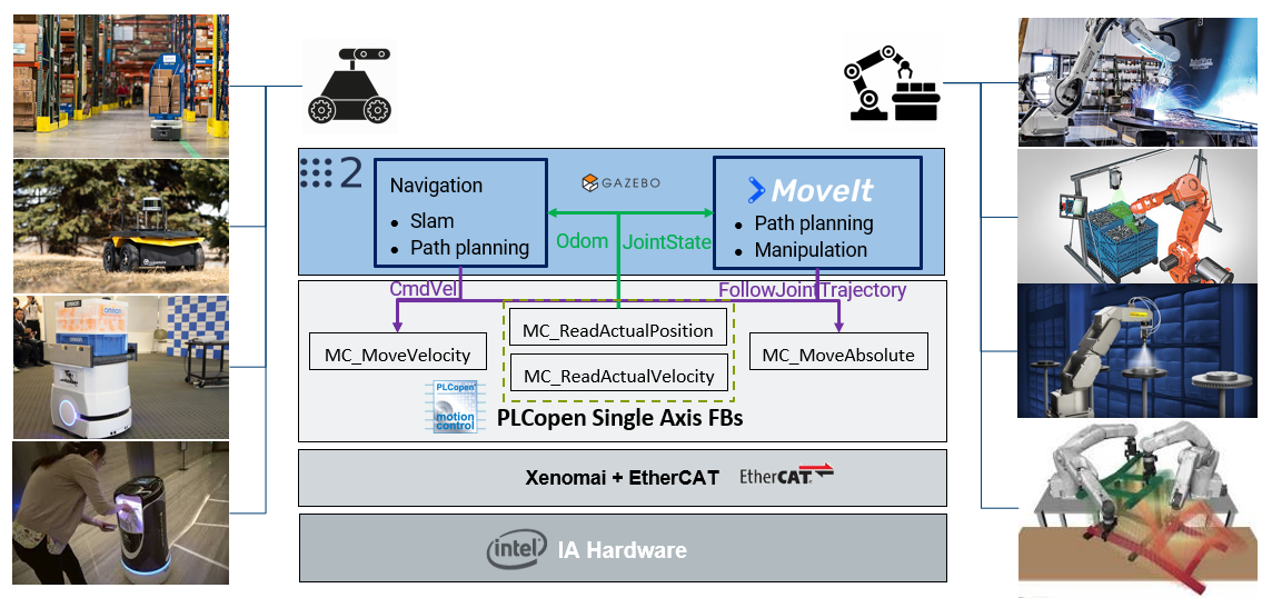
The pictures at the left and right columns are coming from the internet.
In ECI, the concept has been proven in the joint-lab project between SYMG and Intel through controlling an omni-directional AMR with four servo motors by integrating ROS2 navigation, SoftPLC (commercial & open sourced), PLCopen motion function blocks and IgH EtherCAT master stack, and running the whole software stack on ECI optimized real-time linux kernel.
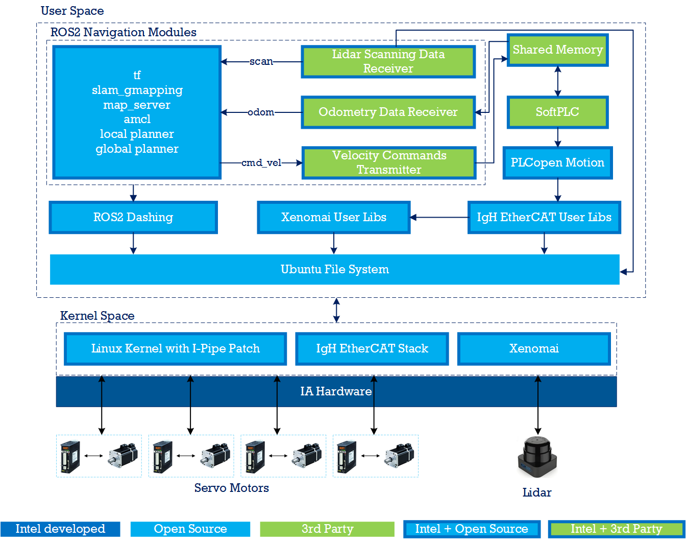
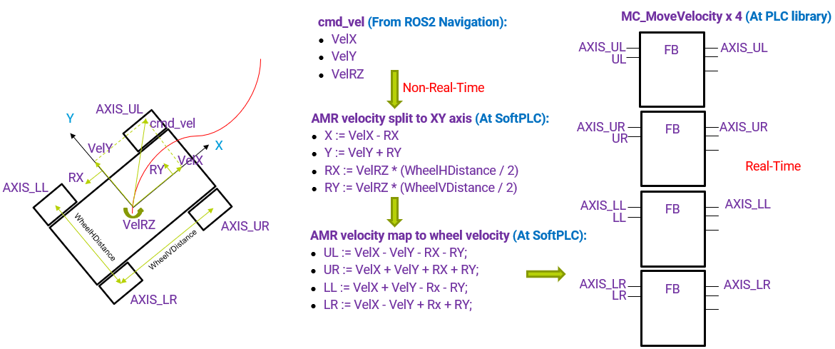
As shown in the above figure, ROS2 navigation plans the global path routine and local trajectory for the AMR to move. When AMR moves, the velocity command cmd_vel calculated by ROS2 Navigation is transmitted to the SoftPLC system through the shared memory. This guarantee the efficient communication and good separation between real-time and non real-time process. The velocity command cmd_vel includes three components indicating the velocities translating forward (VelX), translating sideways (VelY) and rotating round the center of mass (VelRZ) on the 2D plane. The AMR velocity command is parsed and split into the velocities of four Mecanum 4 wheels (UL, UR, LL, LR). The detail of this split process is shown in the below figure. The velocity command of each wheel is input into a MC_MoveVelocty function block to execute. The MC_MoveVelocity function block makes path interpolation between the velocity inputs and sends the command to the servo motor through the IgH EtherCAT stack. At the same time, the SoftPLC calls the function blocks MC_ReadActualPosition and MC_ReadActualVelocity to read the wheel velocity, and synthesize the information into the odometry of AMR. The odometry information is then transmitted back to ROS2 navigation through the shared memory for the SLAM calculation.
The ST program for this application can be found below, which is configured to run in 1ms cycle:
(* Split the AMR velocity into the wheel velocities *)
FUNCTION_BLOCK AGVM_VelCartesian2Wheels
  VAR_INPUT
    VelX :  LREAL;
    VelY :  LREAL;
    VelRZ : LREAL;
  END_VAR

  VAR_OUTPUT
    UL :    LREAL;
    UR :    LREAL;
    LL :    LREAL;
    LR :    LREAL;
  END_VAR

  VAR_EXTERNAL
    WheelHDistance :        LREAL;(**)
    WheelVDistance :        LREAL;(**)
  END_VAR

  VAR
    VelLZ : LREAL;
  END_VAR

  VelLZ := VelRZ * ((WheelHDistance + WheelVDistance) / LREAL#2.0);

  UL := VelX - VelY - VelLZ;
  UR := VelX + VelY + VelLZ;
  LL := VelX + VelY - VelLZ;
  LR := VelX - VelY + VelLZ;
END_FUNCTION_BLOCK

(* Synthesize the wheel velocities into the AMR velocity *)
FUNCTION_BLOCK AGVM_VelWheels2Cartesian
  VAR_INPUT
    UL :    LREAL;
    UR :    LREAL;
    LL :    LREAL;
    LR :    LREAL;
  END_VAR

  VAR_OUTPUT
    VelX :  LREAL;
    VelY :  LREAL;
    VelRZ : LREAL;
  END_VAR

  VAR_EXTERNAL
    WheelHDistance :        LREAL;(**)
    WheelVDistance :        LREAL;(**)
  END_VAR

  VelX := (UL + UR + LL + LR) / LREAL#4.0;

  VelY := (-UL + UR + LL - LR) / LREAL#4.0;
  VelRZ := (-UL + UR - LL + LR) / LREAL#4.0 / ((WheelHDistance + WheelVDistance) / LREAL#2.0);
END_FUNCTION_BLOCK

(* Global variables *)
VAR_GLOBAL
  PLC_SYS_TICK_CNT  AT %MD1.0 :     UDINT;
  PLC_TASK_DEFINED  AT %MW1.4 :     INT;
  PLCMODE_ON        AT %MX1.2016.0 :        BOOL;(*TRUE : current PLC mode is ON*)
  PLCMODE_LOADING   AT %MX1.2017.0 :        BOOL;(*TRUE : current PLC mode is LOADING*)
  PLCMODE_STOP      AT %MX1.6.0 :   BOOL;(*TRUE : current PLC mode is STOP*)
  PLCMODE_RUN       AT %MX1.7.0 :   BOOL;(*TRUE : current PLC mode is RUN*)
  PLCMODE_HALT      AT %MX1.8.0 :   BOOL;(*TRUE : current PLC mode is HALT*)
  PLC_TICKS_PER_SEC AT %MW1.2000 :  UINT;
  PLC_MAX_ERRORS    AT %MD1.2004 :  UDINT;
  PLC_ERRORS        AT %MD1.2008 :  UDINT;
  PLC_TASK_AVAILABLE        AT %MW1.2012 :  INT;
  PLC_SYSTASK_AVAILABLE     AT %MW1.2016 :  INT;
  PLCDEBUG_FORCE    AT %MX1.2018.0 :        BOOL;(*TRUE : current PLC mode is POWER on*)
  PLCDEBUG_BPSET    AT %MX1.2019.0 :        BOOL;(*TRUE : one or more*)
  PLCDEBUG_POWERFLOW        AT %MX1.2020.0 :        BOOL;(*TRUE : current PLC mode is POWER on*)
  WheelVDistance :  LREAL := 0.483;(*Distance between the front and back wheels*)
  WheelHDistance :  LREAL := 0.371;(*Distance between the two side wheels*)
END_VAR

(* Main program *)
PROGRAM main
  VAR
    Acc :   LREAL := 2.0;
    MC_Power_1 :    MC_Power;
    MC_Power_2 :    MC_Power;
    MC_Power_3 :    MC_Power;
    MC_Power_4 :    MC_Power;
    PowStat :       BOOL;
    AxisLL :        DINT := 3;
    AxisLR :        DINT := 4;
    AxisUL :        DINT := 1;
    AxisUR :        DINT := 2;
    RatioLimit :    LREAL := 1.0;
    VAxisULVel :    LREAL;
    VAxisURVel :    LREAL;
    VAxisLLVel :    LREAL;
    VAxisLRVel :    LREAL;
    VAxisMaxVel :   LREAL;
    AxisVelLimit :  LREAL := 0.75;
    MC_EmergencyStop_1 :    MC_EmergencyStop;
    MC_Reset_1 :    MC_Reset;
    TransH :        LREAL;
    TransV :        LREAL;
    Twist : LREAL;
    MC_Reset_2 :    MC_Reset;
    MC_Reset_3 :    MC_Reset;
    MC_Reset_4 :    MC_Reset;
    ENABLE_FLAG :   BOOL;
    MC_Halt_2 :     MC_Halt;
    MC_Halt_3 :     MC_Halt;
    MC_Halt_4 :     MC_Halt;
    MC_MoveVelocity_2 :     MC_MoveVelocity;
    MC_MoveVelocity_3 :     MC_MoveVelocity;
    MC_MoveVelocity_4 :     MC_MoveVelocity;
    MC_Halt_1 :     MC_Halt;
    MC_MoveVelocity_1 :     MC_MoveVelocity;
    SHM_PosX        AT %ML3.200 :   LREAL := 0.0;
    SHM_PosY        AT %ML3.208 :   LREAL := 0.0;
    SHM_PosRZ       AT %ML3.216 :   LREAL := 0.0;
    SHM_VelX        AT %ML3.224 :   LREAL := 0.0;
    SHM_VelY        AT %ML3.232 :   LREAL := 0.0;
    SHM_VelRZ       AT %ML3.240 :   LREAL := 0.0;
    SHM_Error       AT %MX3.248.0 : BOOL;
    MC_ReadAxisError_1 :    MC_ReadAxisError;
    SHM_Enable      AT %MX3.100.0 : BOOL;
    SHM_EmergStop   AT %MX3.101.0 : BOOL;
    SHM_TransH      AT %ML3.102 :   LREAL := 0.0;
    SHM_Twist       AT %ML3.118 :   LREAL := 0.0;
    SHM_TransV      AT %ML3.110 :   LREAL := 0.0;
    MC_SetPosition_1 :      MC_SetPosition;
    MC_ReadActualPosition_1 :       MC_ReadActualPosition;
    AGVM_VelCartesian2Wheels_1 :    AGVM_VelCartesian2Wheels;
    MC_ReadActualVelocity_1 :       MC_ReadActualVelocity;
    MC_ReadActualVelocity_2 :       MC_ReadActualVelocity;
    MC_ReadActualVelocity_3 :       MC_ReadActualVelocity;
    MC_ReadActualVelocity_4 :       MC_ReadActualVelocity;
    AGVM_VelWheels2Cartesian_1 :    AGVM_VelWheels2Cartesian;
    AxisULPos :     LREAL;
    MC_ReadActualPosition_2 :       MC_ReadActualPosition;
    MC_ReadActualPosition_3 :       MC_ReadActualPosition;
    MC_ReadActualPosition_4 :       MC_ReadActualPosition;
    AxisURPos :     LREAL;
    AxisLLPos :     LREAL;
    AxisLRPos :     LREAL;
    AGVM_VelWheels2Cartesian_2 :    AGVM_VelWheels2Cartesian;
    AxisULErr :     WORD;
    AxisURErr :     WORD;
    AxisLLErr :     WORD;
    AxisLRErr :     WORD;
    INIT :  BOOL := TRUE;
    MC_MoveAbsolute_1 :     MC_MoveAbsolute;
  END_VAR

  TransV := SHM_TransV;
  TransH := SHM_TransH;
  Twist := SHM_Twist;

  IF SHM_EmergStop THEN
    SHM_EmergStop := FALSE;
    SHM_Enable := FALSE;
    ENABLE_FLAG:=FALSE;
    MC_EmergencyStop_1(Execute:=FALSE);
    MC_EmergencyStop_1(Axis:=AxisUL,Execute:=TRUE);
    MC_EmergencyStop_1(Execute:=FALSE);
    MC_EmergencyStop_1(Axis:=AxisUR,Execute:=TRUE);
    MC_EmergencyStop_1(Execute:=FALSE);
    MC_EmergencyStop_1(Axis:=AxisLL,Execute:=TRUE);
    MC_EmergencyStop_1(Execute:=FALSE);
    MC_EmergencyStop_1(Axis:=AxisLR,Execute:=TRUE);
  END_IF;

  IF SHM_Enable THEN
    SHM_Enable := FALSE;
    IF NOT PowStat THEN
      MC_Reset_1(Execute:=FALSE);
      MC_Reset_2(Execute:=FALSE);
      MC_Reset_3(Execute:=FALSE);
      MC_Reset_4(Execute:=FALSE);
      ENABLE_FLAG:=TRUE;
    END_IF;
  END_IF;

  IF ENABLE_FLAG THEN
    MC_Reset_1(Axis:=AxisUL,Execute:=TRUE);
    MC_Reset_2(Axis:=AxisUR,Execute:=TRUE);
    MC_Reset_3(Axis:=AxisLL,Execute:=TRUE);
    MC_Reset_4(Axis:=AxisLR,Execute:=TRUE);

    IF MC_Reset_1.Done AND MC_Reset_2.Done AND MC_Reset_3.Done AND MC_Reset_4.Done THEN
      ENABLE_FLAG := FALSE;
    END_IF;
  END_IF;

  MC_Power_1(Axis:=AxisUL,Enable:=TRUE,EnablePositive:=TRUE,EnableNegative:=TRUE);
  MC_Power_2(Axis:=AxisUR,Enable:=TRUE,EnablePositive:=TRUE,EnableNegative:=TRUE);
  MC_Power_3(Axis:=AxisLL,Enable:=TRUE,EnablePositive:=TRUE,EnableNegative:=TRUE);
  MC_Power_4(Axis:=AxisLR,Enable:=TRUE,EnablePositive:=TRUE,EnableNegative:=TRUE);

  PowStat := MC_Power_1.Status AND MC_Power_1.Valid AND
        MC_Power_2.Status AND MC_Power_2.Valid AND
        MC_Power_3.Status AND MC_Power_3.Valid AND
        MC_Power_4.Status AND MC_Power_4.Valid;

  IF PowStat THEN
    IF INIT THEN
      MC_SetPosition_1(Execute:=FALSE);
      MC_SetPosition_1(Axis:=AxisUL,Execute:=TRUE,Position:=LREAL#0.0,Relative:=FALSE,Source:=DINT#1);
      MC_SetPosition_1(Execute:=FALSE);
      MC_SetPosition_1(Axis:=AxisUR,Execute:=TRUE,Position:=LREAL#0.0,Relative:=FALSE,Source:=DINT#1);
      MC_SetPosition_1(Execute:=FALSE);
      MC_SetPosition_1(Axis:=AxisLL,Execute:=TRUE,Position:=LREAL#0.0,Relative:=FALSE,Source:=DINT#1);
      MC_SetPosition_1(Execute:=FALSE);
      MC_SetPosition_1(Axis:=AxisLR,Execute:=TRUE,Position:=LREAL#0.0,Relative:=FALSE,Source:=DINT#1);
      SHM_PosX:=LREAL#0.0;
      SHM_PosY:=LREAL#0.0;
      SHM_PosRZ:=LREAL#0.0;
      AxisULPos:=LREAL#0.0;
      AxisURPos:=LREAL#0.0;
      AxisLLPos:=LREAL#0.0;
      AxisLRPos:=LREAL#0.0;
      INIT:=FALSE;
    END_IF;

    AGVM_VelCartesian2Wheels_1(VelX:=TransV,VelY:=TransH,VelRZ:=Twist);
    VAxisULVel:=AGVM_VelCartesian2Wheels_1.UL;
    VAxisURVel:=AGVM_VelCartesian2Wheels_1.UR;
    VAxisLLVel:=AGVM_VelCartesian2Wheels_1.LL;
    VAxisLRVel:=AGVM_VelCartesian2Wheels_1.LR;

    RatioLimit := LREAL#1.0;
    VAxisMaxVel := ABS(VAxisULVel);

    IF VAxisMaxVel < ABS(VAxisURVel) THEN
      VAxisMaxVel := ABS(VAxisURVel);
    END_IF;

    IF VAxisMaxVel < ABS(VAxisLLVel) THEN
      VAxisMaxVel := ABS(VAxisLLVel);
    END_IF;

    IF VAxisMaxVel < ABS(VAxisLRVel) THEN
      VAxisMaxVel := ABS(VAxisLRVel);
    END_IF;

    IF VAxisMaxVel = LREAL#0.0 THEN
      RatioLimit := LREAL#0.0;
    ELSIF VAxisMaxVel > AxisVelLimit THEN
      RatioLimit := AxisVelLimit / VAxisMaxVel;
    END_IF;

    IF VAxisULVel = LREAL#0.0 THEN
      MC_Halt_1(Execute:=FALSE);
      MC_Halt_1(Axis:=AxisUL,Execute:=TRUE,Deceleration:=Acc);
    ELSE
      MC_MoveVelocity_1(Execute:=FALSE);
      MC_MoveVelocity_1(Axis:=AxisUL,Execute:=TRUE,Velocity:=VAxisULVel * RatioLimit,Acceleration:=Acc,Deceleration:=Acc);
    END_IF;

    IF VAxisURVel = LREAL#0.0 THEN
      MC_Halt_2(Execute:=FALSE);
      MC_Halt_2(Axis:=AxisUR,Execute:=TRUE,Deceleration:=Acc);
    ELSE
      MC_MoveVelocity_2(Execute:=FALSE);
      MC_MoveVelocity_2(Axis:=AxisUR,Execute:=TRUE,Velocity:=VAxisURVel * RatioLimit,Acceleration:=Acc,Deceleration:=Acc);
    END_IF;

    IF VAxisLLVel = LREAL#0.0 THEN
      MC_Halt_3(Execute:=FALSE);
      MC_Halt_3(Axis:=AxisLL,Execute:=TRUE,Deceleration:=Acc);
    ELSE
      MC_MoveVelocity_3(Execute:=FALSE);
      MC_MoveVelocity_3(Axis:=AxisLL,Execute:=TRUE,Velocity:=VAxisLLVel * RatioLimit,Acceleration:=Acc,Deceleration:=Acc);
    END_IF;

    IF VAxisLRVel = LREAL#0.0 THEN
      MC_Halt_4(Execute:=FALSE);
      MC_Halt_4(Axis:=AxisLR,Execute:=TRUE,Deceleration:=Acc);
    ELSE
      MC_MoveVelocity_4(Execute:=FALSE);
      MC_MoveVelocity_4(Axis:=AxisLR,Execute:=TRUE,Velocity:=VAxisLRVel * RatioLimit,Acceleration:=Acc,Deceleration:=Acc);
    END_IF;
  END_IF;

  MC_ReadActualVelocity_1(Axis:=AxisUL,Enable:=TRUE);
  MC_ReadActualVelocity_2(Axis:=AxisUR,Enable:=TRUE);
  MC_ReadActualVelocity_3(Axis:=AxisLL,Enable:=TRUE);
  MC_ReadActualVelocity_4(Axis:=AxisLR,Enable:=TRUE);

  AGVM_VelWheels2Cartesian_1(
    UL:=MC_ReadActualVelocity_1.Velocity,
    UR:=MC_ReadActualVelocity_2.Velocity,
    LL:=MC_ReadActualVelocity_3.Velocity,
    LR:=MC_ReadActualVelocity_4.Velocity);

  SHM_VelX:=AGVM_VelWheels2Cartesian_1.VelX;
  SHM_VelY:=AGVM_VelWheels2Cartesian_1.VelY;
  SHM_VelRZ:=AGVM_VelWheels2Cartesian_1.VelRZ;

  MC_ReadActualPosition_1(Axis:=AxisUL,Enable:=TRUE);
  MC_ReadActualPosition_2(Axis:=AxisUR,Enable:=TRUE);
  MC_ReadActualPosition_3(Axis:=AxisLL,Enable:=TRUE);
  MC_ReadActualPosition_4(Axis:=AxisLR,Enable:=TRUE);

  AGVM_VelWheels2Cartesian_2(
    UL:=MC_ReadActualPosition_1.Position - AxisULPos,
    UR:=MC_ReadActualPosition_2.Position - AxisURPos,
    LL:=MC_ReadActualPosition_3.Position - AxisLLPos,
    LR:=MC_ReadActualPosition_4.Position - AxisLRPos);

  SHM_PosX:=SHM_PosX + (AGVM_VelWheels2Cartesian_2.VelX * COS(SHM_PosRZ) - AGVM_VelWheels2Cartesian_2.VelY * SIN(SHM_PosRZ));
  SHM_PosY:=SHM_PosY + (AGVM_VelWheels2Cartesian_2.VelX * SIN(SHM_PosRZ) + AGVM_VelWheels2Cartesian_2.VelY * COS(SHM_PosRZ));
  SHM_PosRZ:=SHM_PosRZ + AGVM_VelWheels2Cartesian_2.VelRZ;

  AxisULPos:=MC_ReadActualPosition_1.Position;
  AxisURPos:=MC_ReadActualPosition_2.Position;
  AxisLLPos:=MC_ReadActualPosition_3.Position;
  AxisLRPos:=MC_ReadActualPosition_4.Position;

  MC_ReadAxisError_1(Axis:=AxisUL,Enable:=TRUE);
  AxisULErr:=MC_ReadAxisError_1.ErrorID;

  MC_ReadAxisError_1(Axis:=AxisUR,Enable:=TRUE);
  AxisURErr:=MC_ReadAxisError_1.ErrorID;

  MC_ReadAxisError_1(Axis:=AxisLL,Enable:=TRUE);
  AxisLLErr:=MC_ReadAxisError_1.ErrorID;

  MC_ReadAxisError_1(Axis:=AxisLR,Enable:=TRUE);
  AxisLRErr:=MC_ReadAxisError_1.ErrorID;
END_PROGRAM
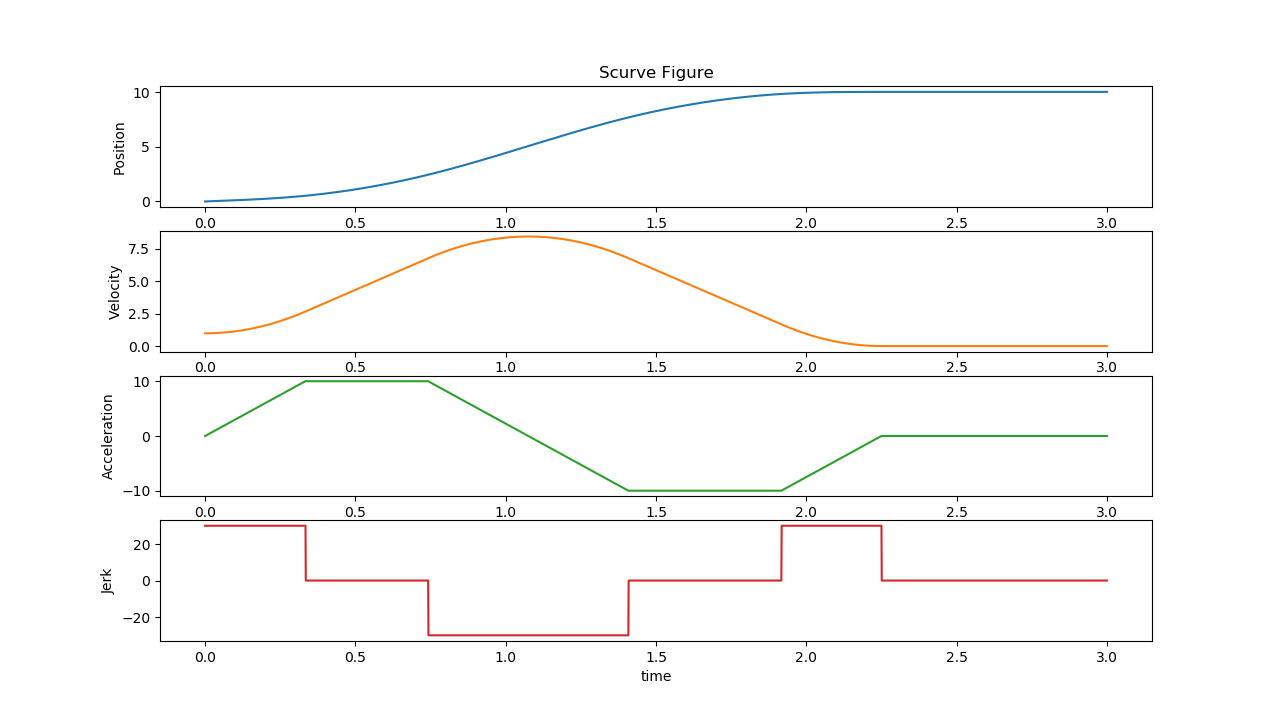
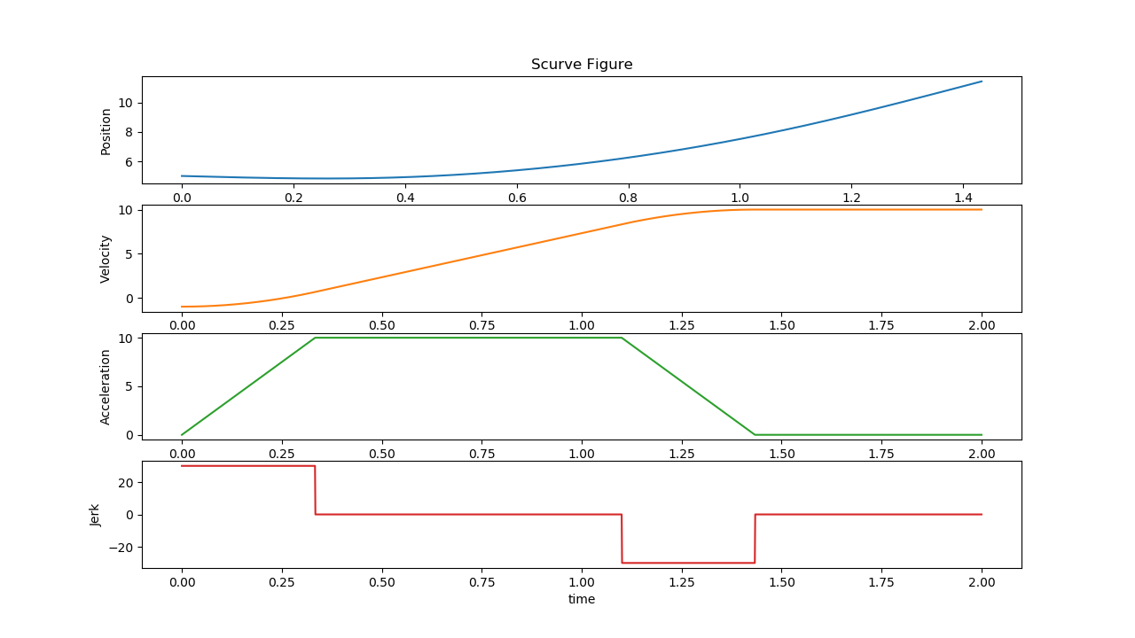
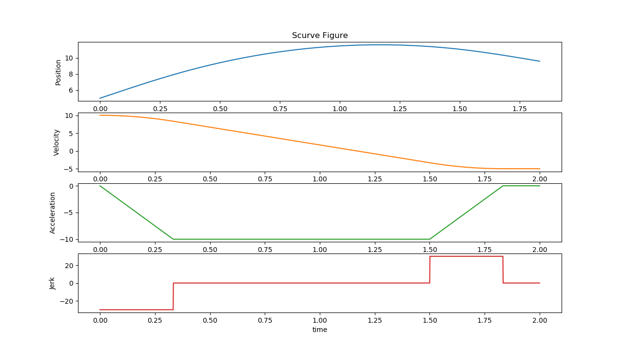
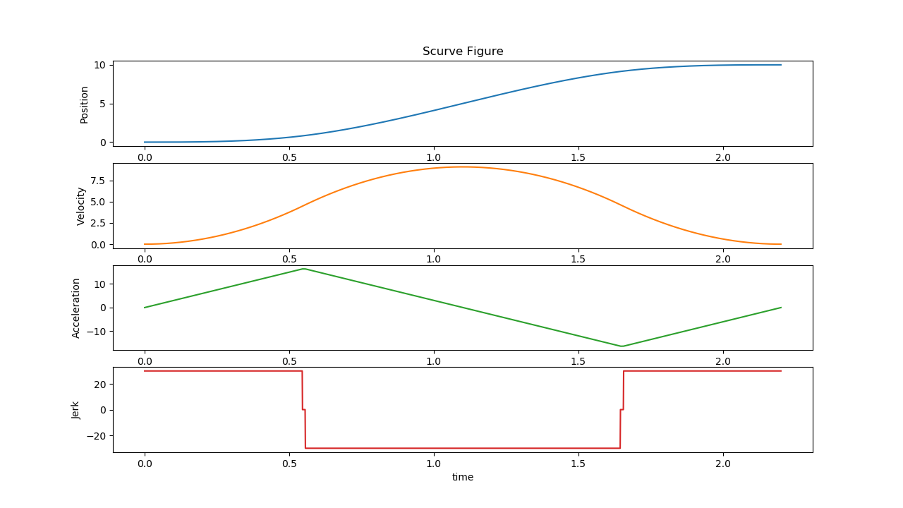
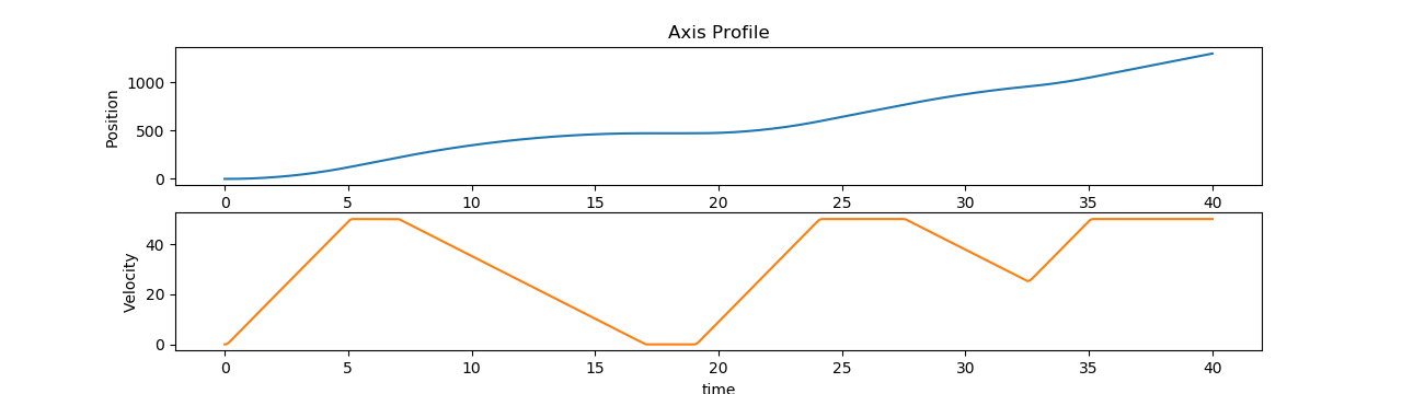
S-curve Trajectory Planning
S-curve trajectory planning is the core function of the PLCopen function blocks for single axis motion control. When driving a motor to an absolute or additive position, the motors always try to accelerate its velocity to its max value and decelerate before it reaches the target position. If the acceleration during this process is not continuous or linear piece-wise, some infinite jerk spikes may happen. For this reason, this trajectory may generate efforts and stresses on the mechanical system of motors that may result detrimental or generate undesired vibrational effects. Therefore, the so called S-curve trajectory planning is necessary.
A sample implementation of the S-curve algorithm is provided in ECI for reference design. For more information of S-curve planning, please refer to “Trajectory Planning for Automatic Machines and Robots-Springer (2008)” by Luigi Biagiotti, Claudio Melchiorri.
PLCopen Motion Sanity-Check Testing
Terminology in the following sections:

S0 - Start position
S1 - End position
V0 - Start velocity
V1 - End velocity
A0 - Start acceleration
A1 - End acceleration
Vmin - Minimum velocity
Vmax - Maximum velocity
Amin - Minimum acceleration
Amax - Maximum acceleration
Jmin - Minimum jerk
Jmax - Maximum jerk
The following section is applicable to:

Sanity-Check #1: On-line S-Curve Algorithm Test
$ /opt/plcopen/online_scurve_test
Expected output
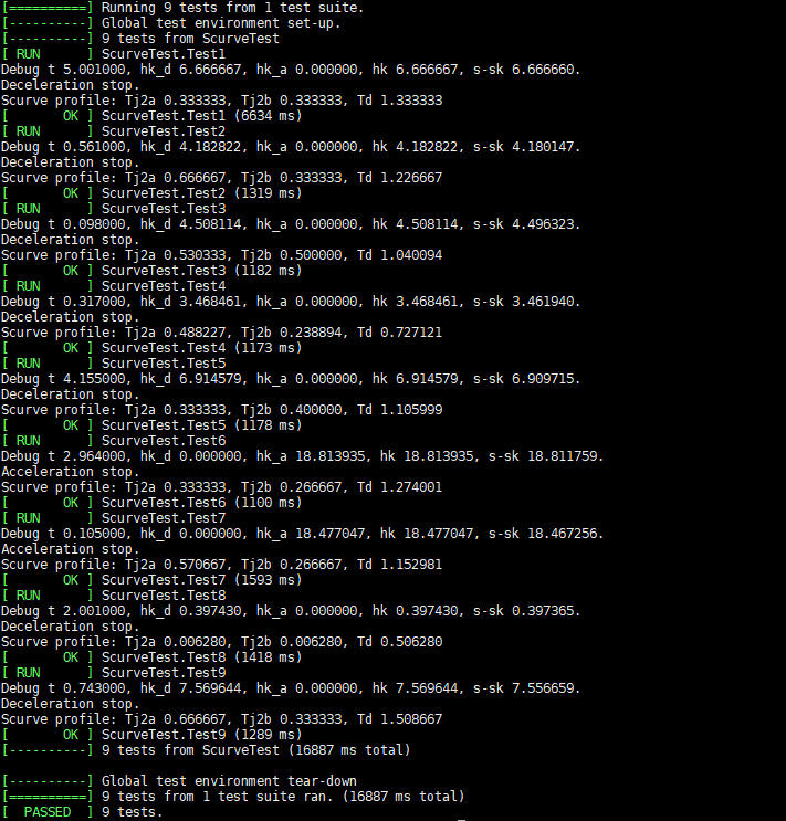
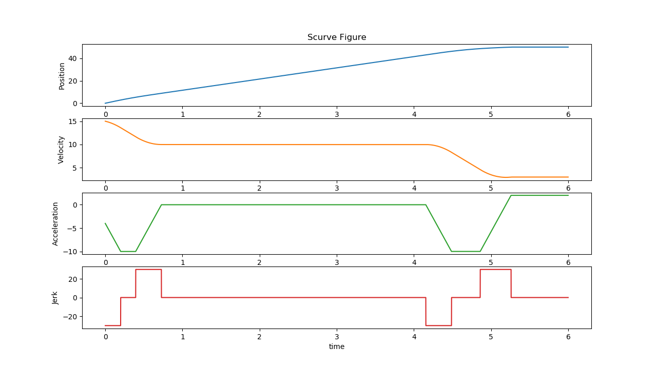
The tests will generate several images, which illustrate the motor trajectory planning under different conditions:
Test1.png
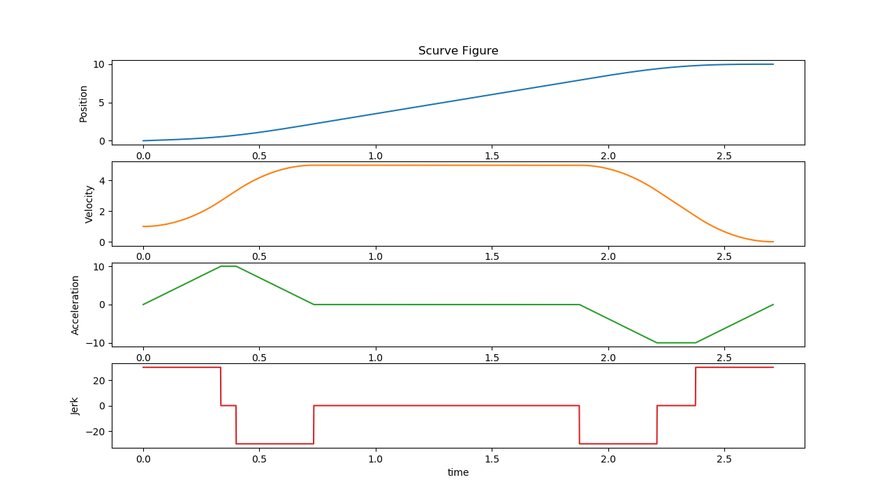
Input:
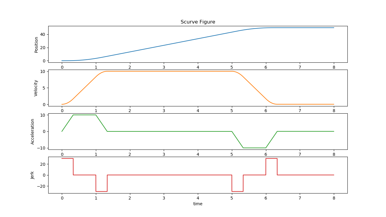
S0: 0, S1: 50, V0: 0, V1: 0, A0: 0, A1: 0Constraints:
Vmin: -10, Vmax: 10, Amin: -10, Amax: 10, Jmin: -30, Jmax: 30
Test2.png
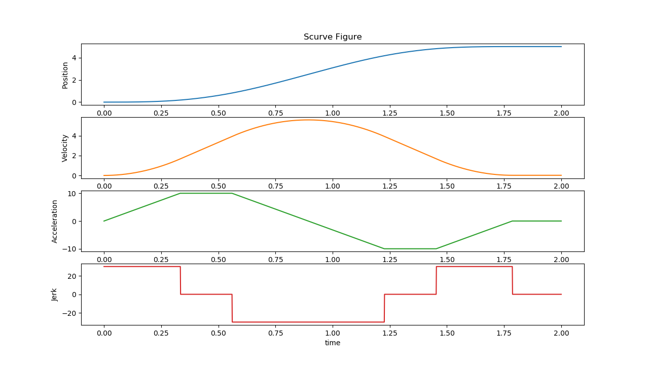
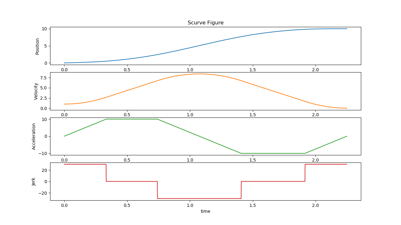
Input:
S0: 0, S1: 5, V0: 0, V1: 0, A0: 0, A1: 0Constraints:
Vmin: -10, Vmax: 10, Amin: -10, Amax: 10, Jmin: -30, Jmax: 30
Test3.png
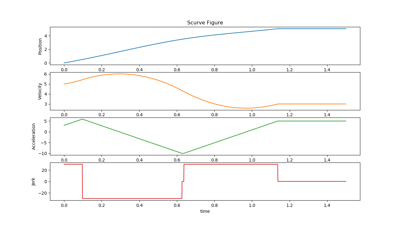
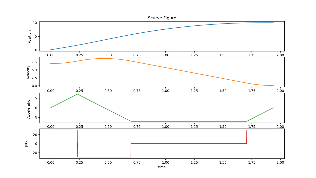
Input:
S0: 0, S1: 5, V0: 5, V1: 3, A0: 3, A1: 5Constraints:
Vmin: -10, Vmax: 10, Amin: -10, Amax: 10, Jmin: -30, Jmax: 30
Test4.png
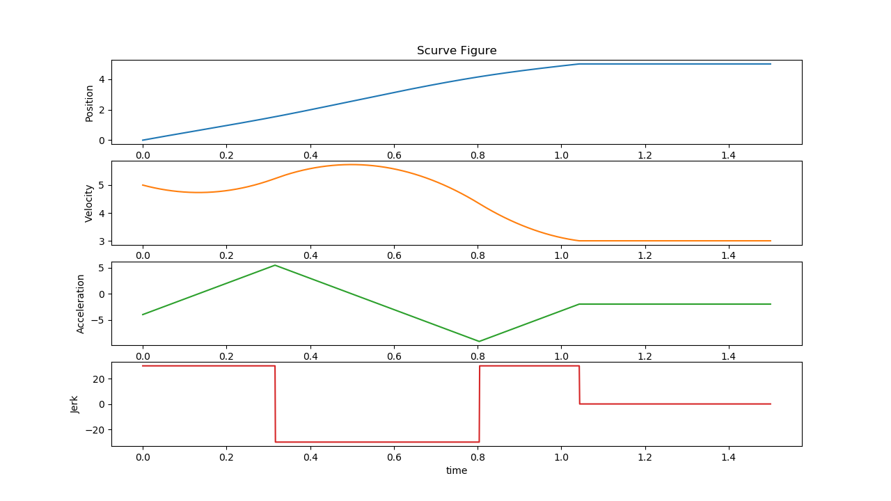
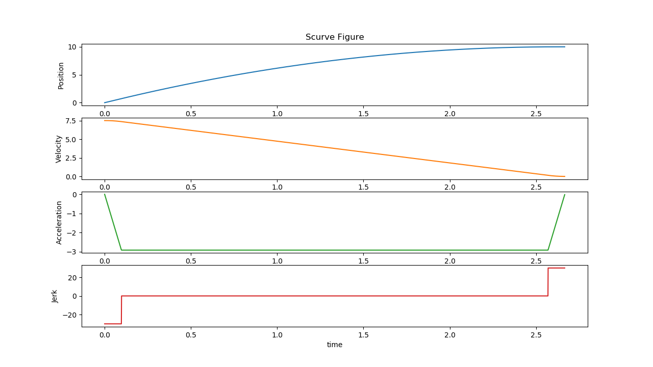
Input:
S0: 0, S1: 5, V0: 5, V1: 3, A0: -4, A1: 2Constraints:
Vmin: -10, Vmax: 10, Amin: -10, Amax: 10, Jmin: -30, Jmax: 30
Test5.png
Input:
S0: 0, S1: 50, V0: 15, V1: 3, A0: -4, A1: 2Constraints:
Vmin: -10, Vmax: 10, Amin: -10, Amax: 10, Jmin: -30, Jmax: 30
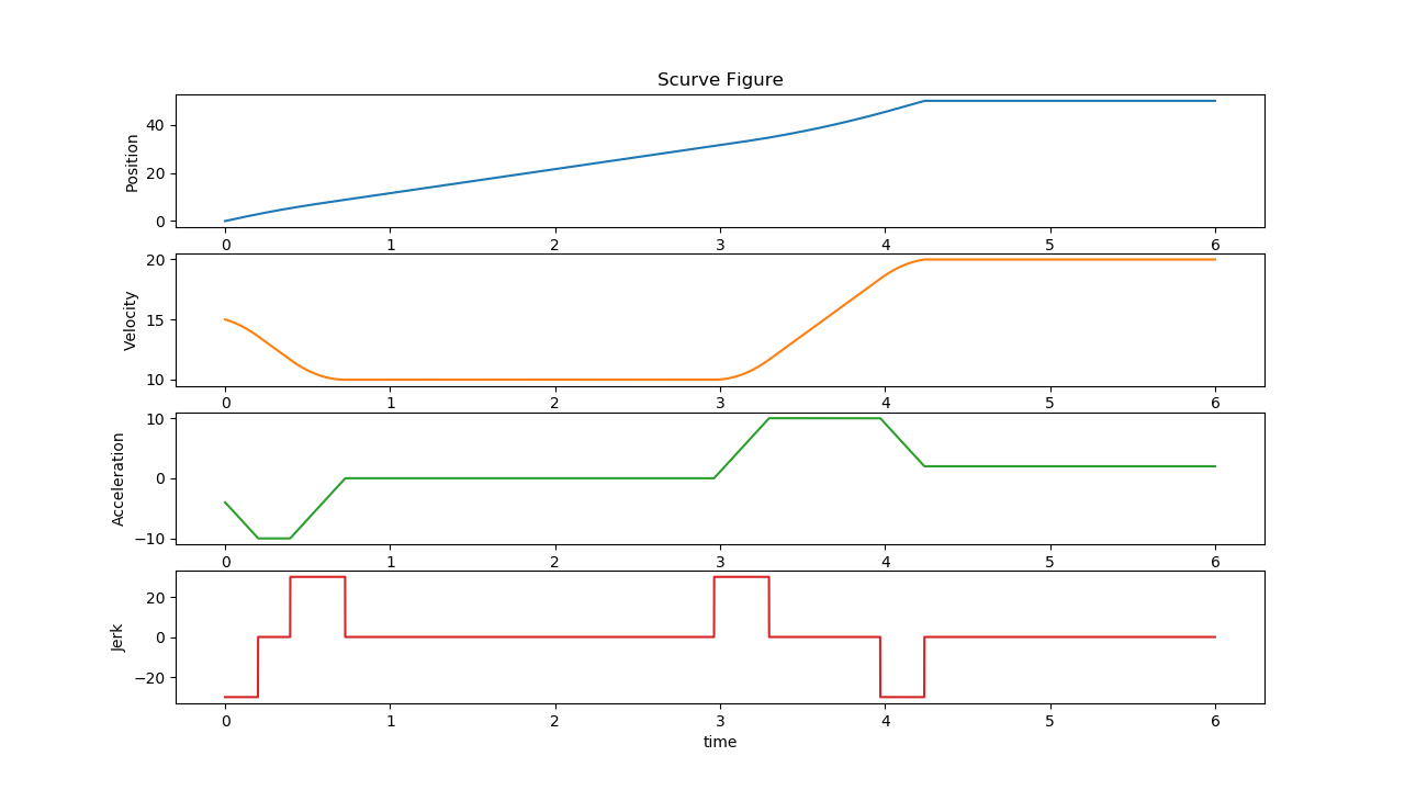
Test6.png
Input:
S0: 0, S1: 50, V0: 15, V1: 20, A0: -4, A1: 2Constraints:
Vmin: -10, Vmax: 10, Amin: -10, Amax: 10, Jmin: -30, Jmax: 30
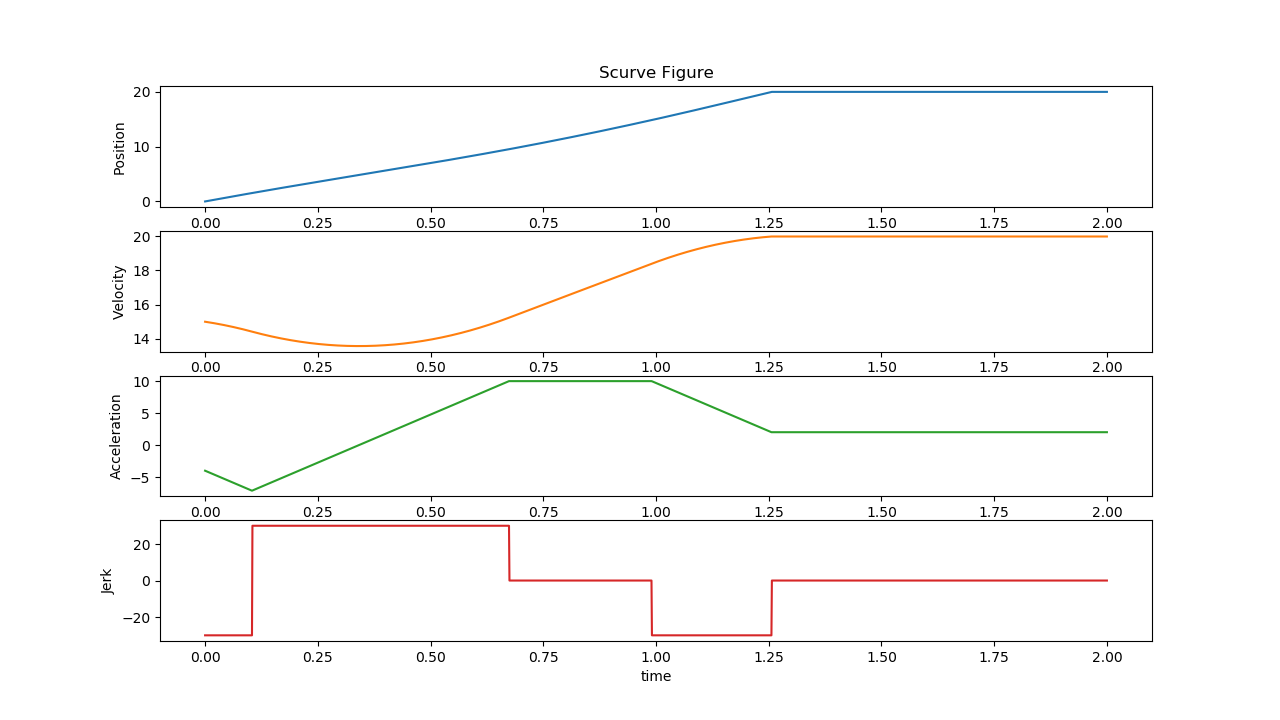
Test7.png
Input:
S0: 0, S1: 20, V0: 15, V1: 20, A0: -4, A1: 2Constraints:
Vmin: -10, Vmax: 10, Amin: -10, Amax: 10, Jmin: -30, Jmax: 30
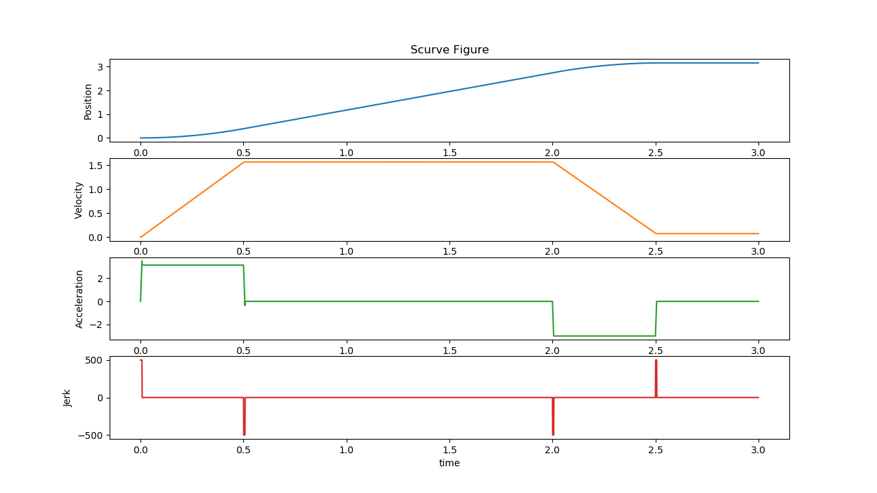
Test8.png
Input:
S0: 0, S1: 3.14, V0: 0, V1: 0, A0: 0, A1: 0Constraints:
Vmin: -1.57, Vmax: 1.57, Amin: -3.14, Amax: 3.14, Jmin: -500, Jmax: 500
Test9.png
Input:
S0: 0, S1: 10, V0: 1, V1: 0, A0: 0, A1: 0Constraints:
Vmin: -10, Vmax: 10, Amin: -10, Amax: 10, Jmin: -30, Jmax: 30
The following section is applicable to:
Sanity-Check #2: Trajectory Planner Test
$ /opt/plcopen/planner_test
Expected output
The tests will generate several images, which illustrate the motor trajectory planning under different conditions:
VelocityUp.png
Input:
S0 5, V0: -1, V1: 10Constraints:
Vmax: 5, Amax 10, Jmax: 30
VelocityDown.png
Input:
S0 5, V0: 10, V1: -5Constraints:
Vmax: 5, Amax 10, Jmax: 30
Example_3_9.png
Input:
S0 0, S1: 10, V0: 1, V1: 0Constraints:
Vmax: 5, Amax 10, Jmax: 30
Example_3_10.png
Input:
S0 0, S1: 10, V0: 1, V1: 0Constraints:
Vmax: 10, Amax 10, Jmax: 30
Example_3_11.png
Input:
S0 0, S1: 10, V0: 7, V1: 0Constraints:
Vmax: 10, Amax 10, Jmax: 30
Example_3_12.png
Input:
S0 0, S1: 10, V0: 7.5, V1: 0Constraints:
Vmax: 10, Amax 10, Jmax: 30
Example_3_13.png
Input:
S0 0, S1: 10, V0: 0, V1: 0Constraints:
Vmax: 10, Amax 20, Jmax: 30
Test_Negative.png
Input:
S0 10, S1: 0, V0: 1, V1: 0Constraints:
Vmax: 5, Amax 10, Jmax: 30
The following section is applicable to:
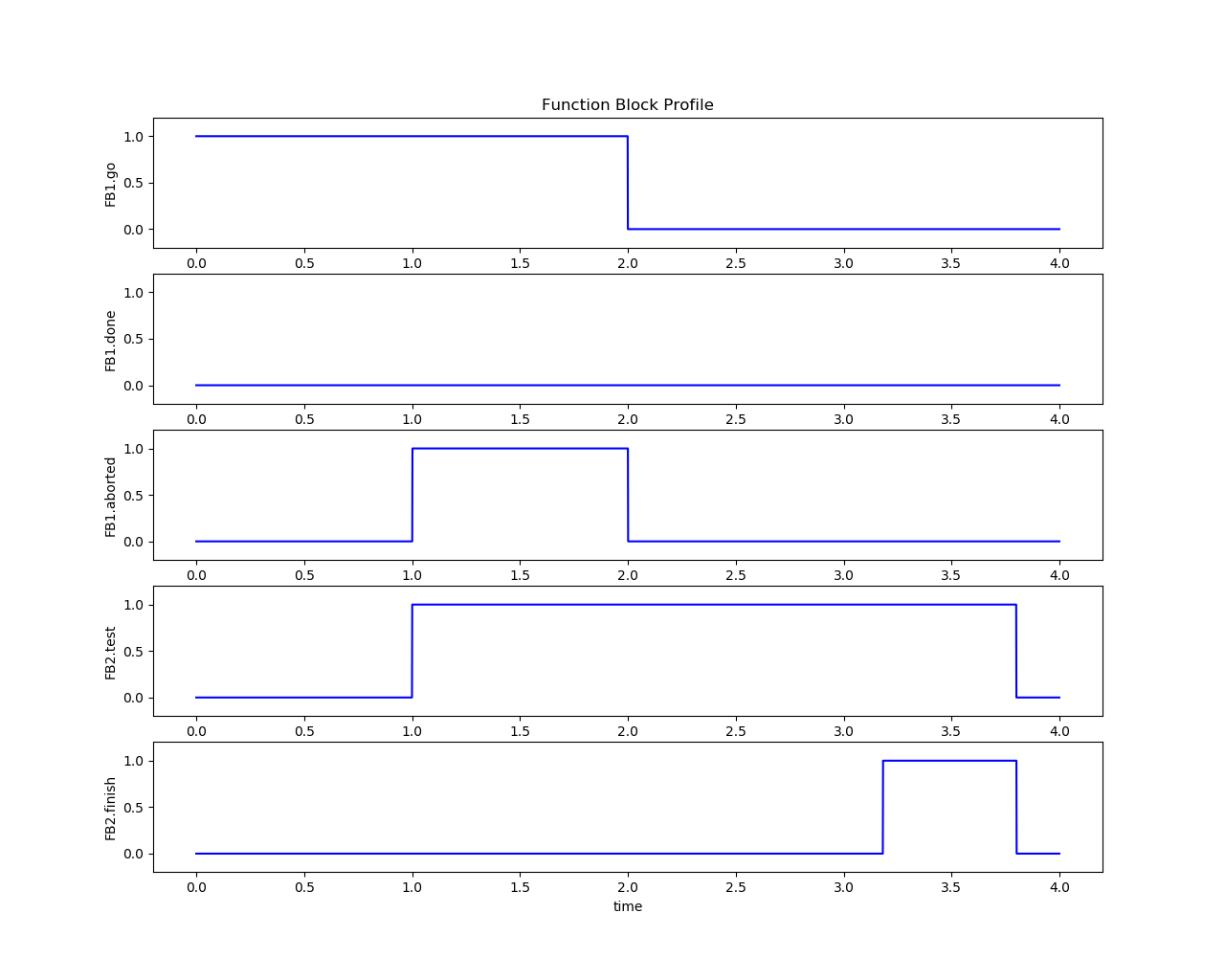
Sanity-Check #3: Function Block Test
$ /opt/plcopen/function_block_test
Expected output
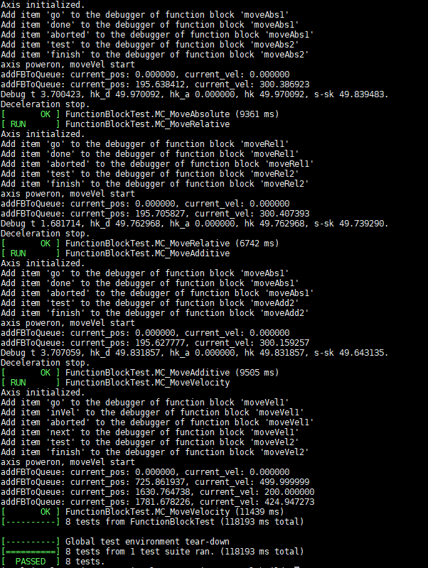
The tests will generate several images, which illustrate the function block execution result and its timing diagram:
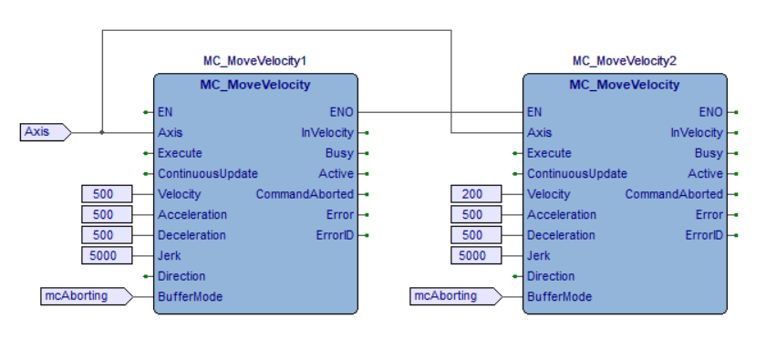
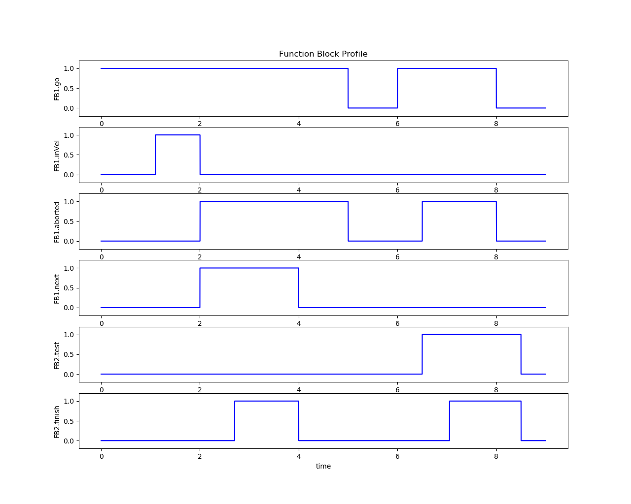
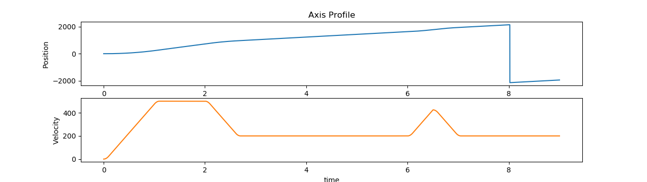
MC_Stop
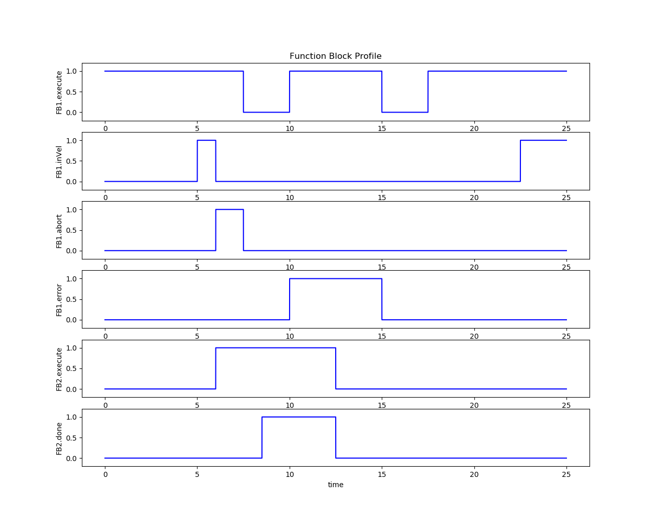
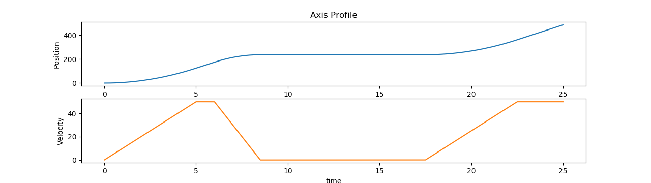
MC_Halt
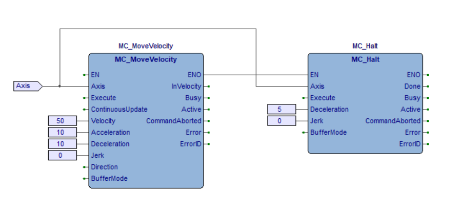
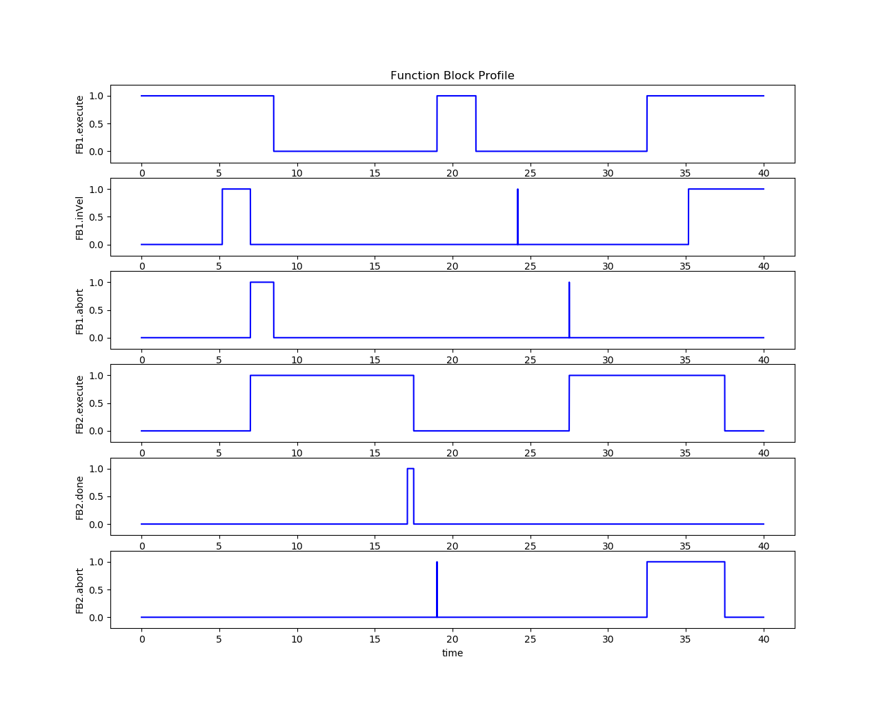
MC_MoveAbsolute


MC_MoveRelative
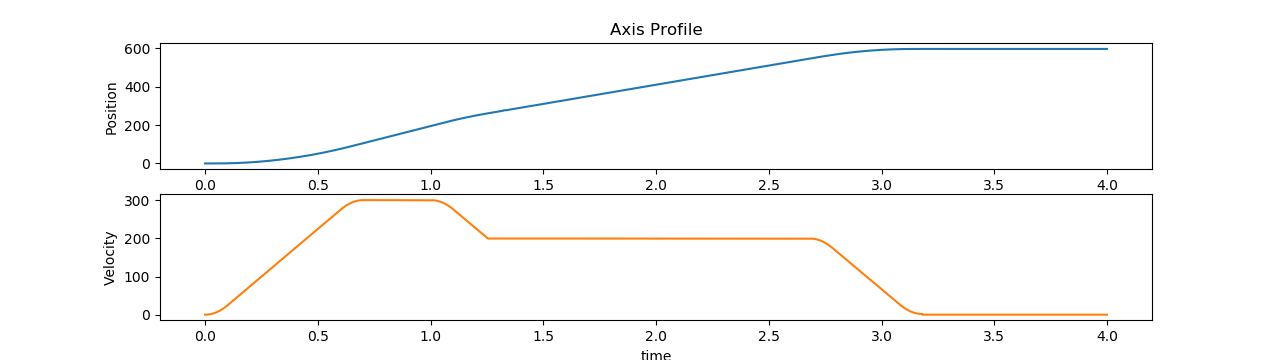
MC_MoveAdditive
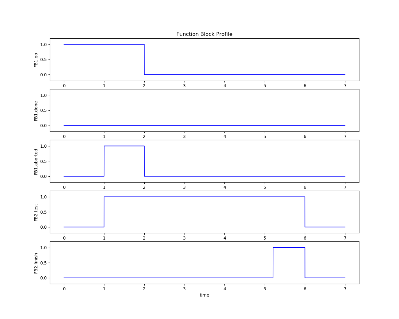
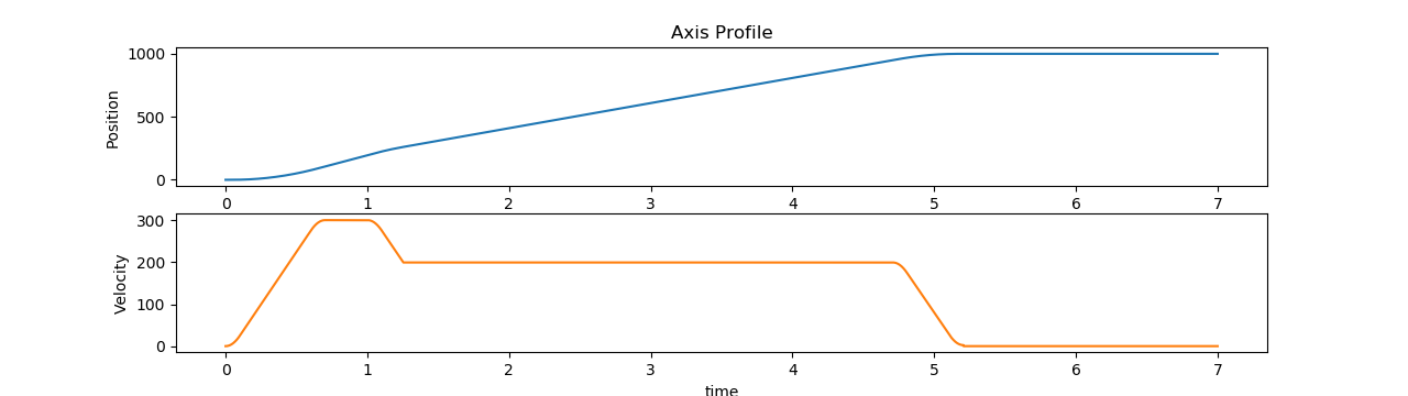
MC_MoveVelocity
PLCopen Motion Recurring Testing
The following section is applicable to:
Recurring Test #1: Latency and jitter benchmarking
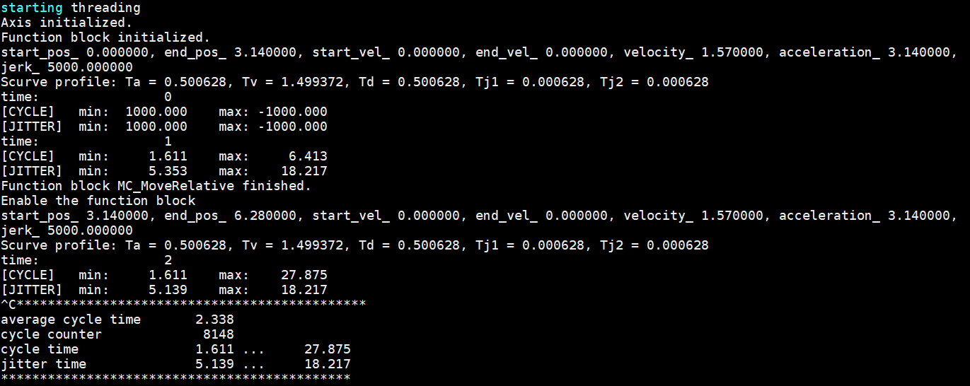
This test will repeat running a MC_MoveRelative function block in 1ms real-time cycle. After running for a while, stop the program by clicking Ctrl+C, then some performance data will show up, which depends on the chosen hardware and configurations.
$ sudo /opt/plcopen/single_axis_move_relative
Expected outputs are similar to: