Setup Three
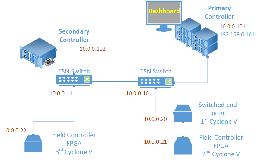
This setup combines the configuration of the Industrial PCs (IPCs) and switches presented in Setup One and the setup of the Cyclone V boards presented in Setup Two. In a similar way, the steps to connect and configure the nodes are reused here. In this setup, the TSN dashboard is run on the Primary controller.
The following figure shows the schematics of this setup with the real-time communication network in red.
Setup Three: Hardware Bill of Materials
The following is the hardware used for the NGSF demo. If you use other hardware, you may need to do additional configuration steps that are not described in this section.
Two IPCs. The demo setup uses Kontron* models.
Three Cyclone® V SoC Development Kits and Intel® SoC FPGA Embedded Development Suite
One PC with Linux. The demo setup uses Ubuntu* 20.04
Six network cables (shown in red in the figure)
One network cable (shown in blue in the figure)
Two TSN switches: TTTech* Edge IP Solution board
Setup Three: Software Bill of Materials
Intel® Edge Controls for Industrial
main_ctrl_appsec_ctrl_appsec_ctrl_fpga_apptsn_dashboardConfiguration files for IPC nodes
Configuration files for TSN switches
Configuration files for Cyclone V
Cyclone V Linux Stack. For details on how to generate this stack, contact Intel Programmable Solutions Group Support, using “Contact us” on the webpage.
Script files
Ubuntu 20.04
Setup Three: Assembly
The starting point for this setup is Setup Two. To advance into this setup, a TSN switch and an additional Cyclone V board are added. To do so, configure the IP addresses of both as presented in Setup One: Interface Setup for the switch and in Setup Two: Interface Setup for the Cyclone V boards.
Setup Three: Preparation
If you are starting from Setup Two, half of the system is already configured and ready to run. You need to configure an additional switch and an additional Cyclone V board.
On the Primary controller, connect the additional switch to the maintenance Ethernet interface and configure it with the IP address 10.0.0.10/24 in the same way you configured the other TSN switch. For example, test the connection to the switch via ssh using the default IP address 192.168.0.1/24:
ssh root@192.168.0.1
Set the IP address to 10.0.0.11/24 by editing the file /etc/network/interfaces:
auto SE01
iface SE01 inet static
address 10.0.0.11
netmask 255.255.255.0
Reboot the switch:
reboot
Now, from one of the end nodes, where all collateral can be found, run the following command:
ssh root@10.0.0.11 ‘mkdir -p /root/config/’
scp -r config/switch/ root@10.0.0.11:/root/config/.
Connect the switch to the TSN switch that is already connected to the other two Cyclone V boards.
Add the secondary node to the newly added switch as shown in the above figure.
Try to connect to the Secondary controller from the primary one by running the following command:
ssh root@10.0.0.102
Close the connection.
Now, it is time to prepare the third Cyclone V board in the setup. Do the same preparation that you did for the TSN switch -connecting it to the maintenance Ethernet interface of the Primary controller. Also set the IP address to 10.0.0.22/24. That is, connect to the Cyclone V board using the default IP address 192.168.0.1/24:
ssh root@192.168.0.1
Set the IP address to 10.0.0.22/24 by editing the /etc/network/interfaces file:
auto SE01
iface SE01 inet static
address 10.0.0.22
netmask 255.255.255.0
Reboot the switch:
reboot
Connect it to the switch closer to the Secondary controller.
At this point, all machines should be reachable on the TSN network. Consider the following table and try connecting to all devices starting from the Primary controller.
End Node |
TSN IP (Interface) |
Management Network (Interface) |
Node ID |
|---|---|---|---|
Ubuntu Box |
10.0.0.2 (eth0) |
-1 |
|
TSN Switch |
10.0.0.10 |
||
Primary Controller |
10.0.0.101 (eth1) |
192.168.0.101 (not used) |
0 |
Secondary Controller |
10.0.0.102 (TBD) |
1 |
|
First Cyclone V |
10.0.0.20 (SE01) |
4 |
|
Second Cyclone V |
10.0.0.21 (SE01) |
5 |
|
Third Cyclone V |
10.0.0.22 (SE01) |
6 |
Now, it is time to configure the TSN features, on the whole system, starting with the primary and secondary nodes.
Next, set up the host on the Primary controller. As the clocks and host were set before successfully, it is possible to proceed directly to the setup_host, after you query the date of the switch to be sure that the clocks are synchronized. To confirm this, log into the switch running the following command:
ssh root@10.0.0.11
Then, run the following command:
date
Capture the result value and change the date of the Primary controller:
date -s “$RESULT ABOVE”
Now, you can setup on the Primary controller. Log in to the Primary controller and run the following commands:
cd config
setenv ./setup_environment.sh
setup_host
To verify the status of ptp4l and phc2sys status, run the following commands:
tail -l /tmp/ptp4l.log
tail -l /tmp/phc2sys.log
Next, set up the secondary host, repeating the procedure above for the Secondary controller, up to the step that checks the clocks.
Now, check the clocks on all systems. Open a shell for each machine and run the date command. The output must be similar for all clocks.
Set the switches to the default setting as done in Setup One, as in Setup One: Interface Setup, remembering that in this setup there are two switches. Also, configure the Cyclone V board, following the instructions provided in Setup Two: Interface Setup.
The next step is to configure the applications.
Setup Three: Application Configuration
Since the configuration for the other setups are already done, the only configuration step needed is related to the third Cyclone V board. Change the endnodeID in the configuration file, reflecting the node IDs listed in the above table. After copying sec_ctrl_fpga_app and the ngsf.json file to the third Cyclone V board, modify it to have the endnodeID as values for the respective node IDs.
Setup Three: Running the Applications
Prepare to run the applications.
Copy the following:
main_ctrl_appto theappfolder of the Primary controllersec_ctrl_appto theappfolder of the Secondary controllertsn_dashboardto the Linux systemngsf.jsonfile to the same folder containingmain_ctrl_app,sec_ctrl_app, andtsn_dashboard
On the Primary controller, run the following commands:
cd app
NGSFDBG=”True” ./main_ctrl_app
Similarly, on the Secondary controller, run the following commands:
cd app
NGSFDBG=”True” ./sec_ctrl_app
Also, on the Cyclone machines, run the following commands:
cd app
./sec_ctrl_fpga_app ngsf.json
On the Linux box, run the following commands:
cd app
sudo ./tsn_dashboard
By default, traces should appear on the dashboard. Use the Preferences tab to customize the fields that must be plotted for the live data and long-term graphs.
Run the following commands to stop the applications at any time:
killall -9 main_ctrl_app
killall -9 sec_ctrl_app
Similarly, run the following command to kill the applications on Cyclone V:
killall -9 sec_ctrl_fpga_app