Configuration
For the complete setup to work and to enable measurements, you must configure the devices and applications.
As a mandatory first step, prepare the Industrial PCs (IPCs) for real-time applications by changing the BIOS options.
Next, configure the supporting applications that run continuously, for example, PTP4L and PHC2SYS, which are used for maintaining device clock synchronization.
Configuration of the OPC UA message exchange requires that the publisher and subscribers share some parameters. Some of those parameters are also used to configure the Ethernet devices, as the details of the devices used are already available in the software configuration file.
Most applications in the setup share the same configuration, hence a more elaborate design was used by applying a single file, the ngsf.json file, to describe the setup and the communication between applications. To know more about the design, refer to :ref:`ngsf.json File`.
Time Sensitive Networking (TSN) configuration is complicated by the fact that the IPCs and the FPGAs use different stacks, making the configuration of their respective Ethernet devices different. Also, the TSN bridges require a different configuration.
The configuration of the Ethernet devices uses a static script, instead of using parameters already set in the ngsf.json file.
The following sections provide details on the recommended BIOS settings, software configuration using the ngsf.json file, and TSN setup.
BIOS Configuration
Time sensitive networking also requires optimized real-time capabilities. You must configure the BIOS on the IPCs to tune for the best real-time performance. The following table lists the real-time guides for the supported platforms along with the sections to be used in tuning the BIOS.
| Platform | Real-time Tuning Guide | BIOS Tuning Section |
|---|---|---|
| Intel Atom® Processor E3900 Series | Intel, Intel Atom® Processor E3900 Series (Apollo Lake-I) Real-Time Features - Platform Tuning Guide - NDA, 2021 Doc ID: 575548 Contact your Intel representative. |
4 and 5 |
| Intel Atom® x6000E Series Processors | Intel Atom® x6000E Series Processors Real-Time Tunning Guide, 2021 | 6 and 7 |
| 11th Gen Intel® Core™ Processors | 11th Gen Intel® Core™ Processors Real-Time Tuning Guide, 2021 | 6 and 7 |
Configure the BIOS for the platform prior to any further action.
ngsf.json File
The system is complex and consists of several nodes and multiple parameters shared between applications. Hence, the designed approach allows configuration during application initialization and also represents the complete setup in a single file, named ngsf.json.
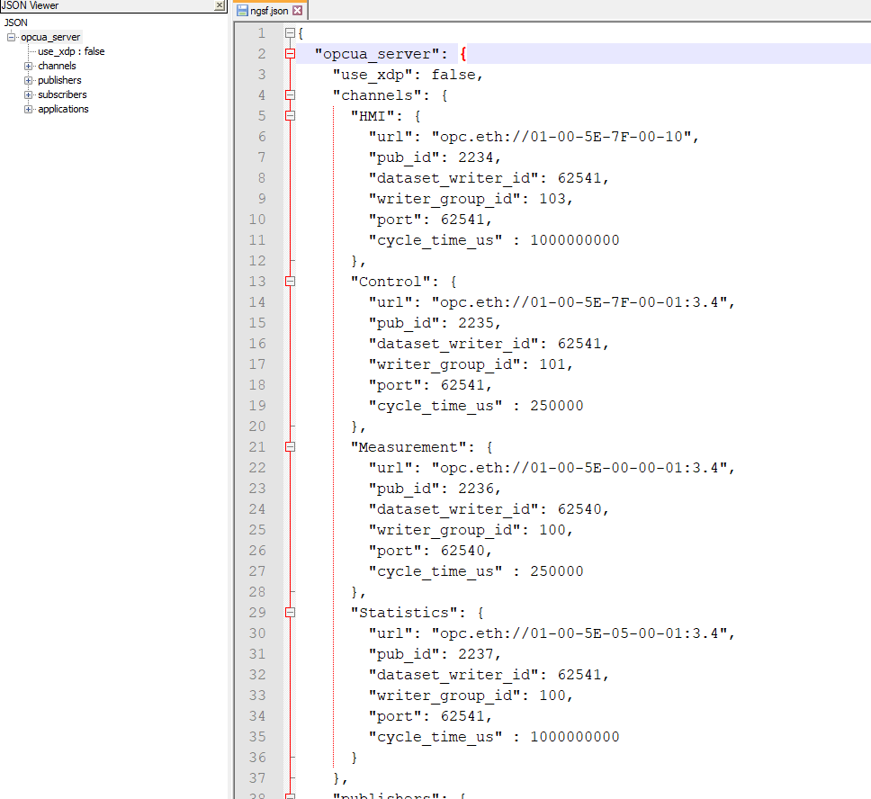
The following figure shows the Global Scope, Channels, Publishers, Subscribers, and Applications sections of the configuration file.
Hierarchically, applications are composed by zero or more Publishers, Subscribers, or both. Publishers and subscribers of a class of message are related to a channel. Channels are configurations shared by publishers and subscribers of the same kind of message. The following figure shows how a Publisher/Subscriber is associated to a channel. A channel can be associated to several Publishers or Subscribers.

The highest level of the configuration file is the opcua_server. The use_xdp parameter of the global scope is not in use. Instead, a new parameter is added in the instances of Publishers and Subscribers within an application.
There is a channel for each type of message used in the communication. The following image shows the messages HMI, Control, Measurement, and Statistics.
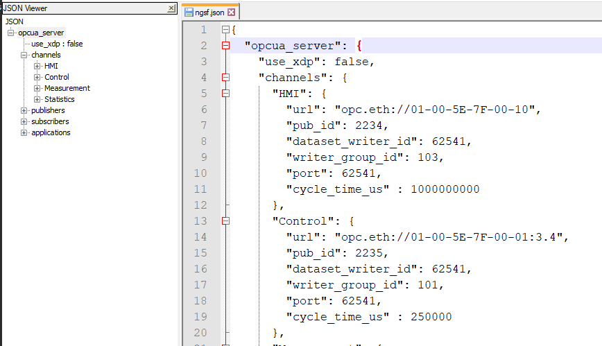
A channel has the following fields: url, pub_id, dataset_writer_id, writer_group_id, port, and cycle_time_us. The meaning and usage of the fields are linked to the Open62541 structure members as listed in the following table.
Channel Field Name |
Open62541 Publisher Fields |
Open62541 Subscriber Fields |
|---|---|---|
url |
UA_NetworkAddressUrlDataType |
UA_NetworkAddressUrlDataType |
pub_id |
UA_PubSubConnectionConfig::publisherId.numeric |
UA_DataSetReaderConfig::publisherId.data |
dataset_writer_id |
UA_DataSetWriterConfig::dataSetWriterId |
UA_DataSetReaderConfig::dataSetWriterId |
writer_group_id |
UA_DataSetReaderConfig::writerGroupId |
UA_DataSetReaderConfig::writerGroupId |
port |
Used on: UA_ServerConfig_setMinimal |
Used on: UA_ServerConfig_setMinimal |
cycle_time_us |
UA_DataSetReaderConfig::publishingInterval |
UA_DataSetReaderConfig::subscribingInterval |
The following figure shows the relation between Publishers and Subscribers, and the channel.
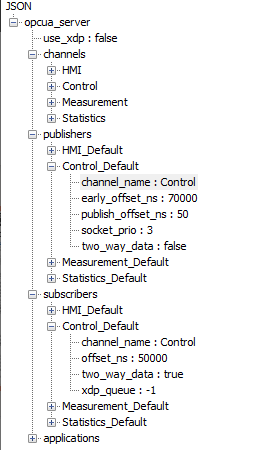
For the Publisher, the fields are: channel_name, early_offset_ns, publish_offset_ns, socket_prio, two_way_data. The following table lists the usage of these fields.
Field |
Usage |
|---|---|
Channel_name |
Channel used for the Publisher |
early_offset_ns |
Used in connection with ETF and value is added at the Transmission time |
publish_offset_ns |
Not in use |
socket_prio |
Setting the socket priority on the Connection options |
two_way_data |
Not in use |
In the Subscriber sections, the fields are: channel_name, offset_ns, two_way_data, and xdp_queue. Only channel_name is currently used to indicate the channel used. The other parameters will be enabled in future versions of NGSF.
The applications sections in the ngsf.json file assign Publishers and Subscribers to an instance and defines some characteristics of the application. An application has instances of Publishers and Subscribers and configurations of itself that are represented by parameters on the application global scope. The following figure shows the configuration of the main_control_app application as an example of the fields and sections belonging to this application.
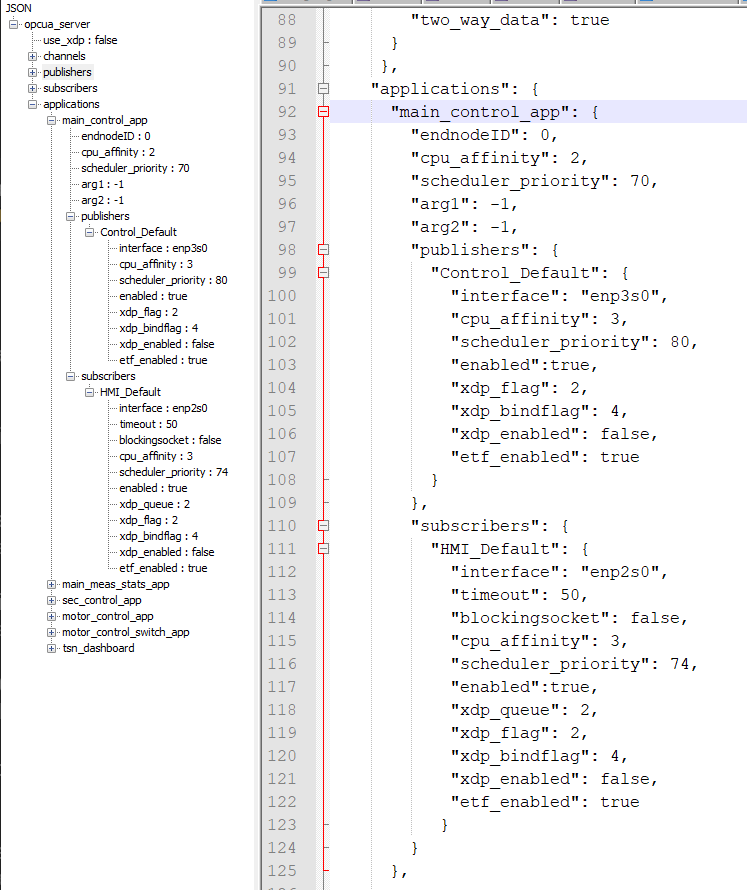
An instance of the Publisher has the following fields: interface, cpu_affinity, scheduler_priority, enabled, xdp_flag, xdp_bindflag, xdp_enabled, and etf_enabled. The following table lists the fields and its usage.
Field |
Usage |
|---|---|
|
Network interface used by the publisher |
|
CPU core that the publisher should run on |
|
Priority provided for the scheduler for the publisher thread |
|
Enable or disable the publisher |
|
Set the XDP flag |
|
Set the bind flag for the XDP – Valid if |
|
Enable XDP for publishing |
|
Enable ETF publishing |
The Subscriber instance has the following parameters for the configuration: interface, timeout, blockingsocket, cpu_affinity, scheduler_priority, enabled, xdp_queue, xdp_flag, xdp_bindflag, xdp_enabled, and etf_enabled. The following table lists the parameters and its usage.
Field |
Usage |
|---|---|
|
Network interface used by the publisher |
|
Valid if not in blocking mode and represents the time window. It is the timeout for receive to wait for the packets. |
|
Block the socket waiting for messages |
|
Core that the publisher should run on |
|
Priority provided for the scheduler for the subscriber thread |
|
Enable or disable the subscriber |
|
Queue used by XDP |
|
Set the XDP flag |
|
Set the bind flag for the XDP – Valid if |
|
Enable XDP for subscribing |
|
Not applicable – will be removed |
The values allowed for the xdp_flag and xdp_bindflag are based on the Linux kernel headers. The following table lists the current values for the flags and the header files in which the values are defined. Note that the values may change in the future as newer kernels (which are directly linked to the driver implementation) may be used.
Field |
Linux Kernel Header |
Values |
|---|---|---|
|
|
XDP_FLAGS_SKB_MODE (1 << 1) XDP_FLAGS_DRV_MODE (1 << 2) XDP_FLAGS_HW_MODE (1 << 3) XDP_FLAGS_REPLACE (1U << 4) |
|
|
XDP_SHARED_UMEM (1 << 0) XDP_COPY (1 << 1) XDP_ZEROCOPY (1 << 2) |
The values arg1 and arg2 are used in some applications with a defined meaning to simplify turning ON a setup on the FPGA applications, allowing you to choose the orientation and the offset of the disc.
Application |
|
|
|---|---|---|
|
Orientation for the motor rotation, use 1 for clockwise or -1 for counterclockwise |
Physical offset in degrees (permit alignment on the software side) |
Changing some fields in the ngsf.json might require changes on the TSN or interface configuration. The following table lists the required changes.
Parameter |
Section |
Influence |
|---|---|---|
interface |
Application::Publisher Application::Subscriber |
Interface used for the TSN must also be changed. |
url |
Channel |
The URL is a mac address that must be configured. The URL also carries the PCP and VLAN ID. If this parameter is changed, the FPGAs and Bridges will need to be reconfigured. |
xdp_queue |
Queue used for the Express Data Path |
If changed in the |
Consider these fields while configuring the setup.
When you are configuring the applications, note the usage of the Publishers and Subscribers for Statistics_Default and Measurement_Default, as these are mutually exclusive. If both are enabled, only Statistics will be published. Measurements are sent for every received control message and Statistics publishes statistics of the measurements every one second.
If you choose to use Measurements, all applications must have Measurements_Default enabled and Statistics_default disabled. For the list of fields that need to be changed to fulfill a given setup, refer to Building NGSF.
TSN Configuration
You must configure all hardware ingredients that have connectivity and evaluate any hardware dependencies with the configuration scripts.
As a first requirement for TSN, the complete network must have the same understanding of time. Reserved time slots must be granted to the time sensitive traffic, while allowing bandwidth for the best effort traffic.
On all network components, that is, IPCs, FPGAs, and bridges, the network clocks must be synchronized, and the network interfaces must be configured to enable both time sensitive and best effort traffic. System clock and network clocks must also be synchronized on IPCs and FPGAs. This synchronization is automatically done by the software stack on the FPGAs.
In addition to the clock synchronization, which is a fundamental requirement for the whole setup, other settings such as the application cycle time, VLAN ID, and PCP are also important.
This section explains the basics on how the provided components are used to perform the TSN configuration for the IPCs, FPGAs, and bridges.
Industrial PCs
On the IPC side, the following files are provided to configure the network: config, taprio.sched, setup_system.sh, gPTP_EHL.conf, gPTP_TGL.conf.
For setups based on discrete cards, such as Intel® Ethernet Controller I210 or Intel® Ethernet Controller I225, the gPTP_TGL.conf file can be used. The config file defines the main parameters for configuring the system. The taprio.sched file defines the schedule for the time aware priority scheduler. The setup_system.sh file processes the information from these two files and configures the platform.
The following figure shows the list of configuration files.
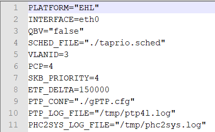
The fields include:
PLATFORM: Values are EHL and TGL for the respective integrated MACs and i225 and i210 for the discrete cards
INTERFACE: Represents the OS adapter name to be used with TSN
QBV: Enables the time aware shaping using the
taprio.schedfileSCHED_FILE: Points to a file containing a list of
taprio.schedand is required if QBV is enabled (the following is an example)sched-entry S 02 250000 sched-entry S 05 750000
The entries on the
taprio.schedfile are used in thetc qdisccommand. In the entries:S stands for setting
02 and 05 stand for the gate masks
250000 and 750000 for the time, in nanoseconds, during which the gate mask will be open (for more information, refer to Time Aware Priority Shaper, 2021.
VLANID and PCP: Refers to the VLAN ID and Priority Code Point values used when configuring the URL for the Publisher and Subscriber sections on the application
SKB_PRIORITY: Indicates the value the socket priority used
ETF_DELTA: Indicates is the amount of time, in nanoseconds, the driver will wake up before the next sending cycle
PTP_CONF: Names the configuration file to be used for
ptp4l. As a reference,gPTP_EHL.conf,gPTP_TGL.conf,gPTP_i210.conf, andgPTP_i225.confare provided for their respective integrated or discrete NICs.
To apply the configuration, set the parameters in the config file according to the end node, following the guidelines described above. In the repository, the parameters are in the config directory and in ECI the parameters are in /opt/intel/ngsf/config. The files must be copied to the end nodes and the usual path is config in the user home directory.
From the directory where the files are located, sourcing setup_system.sh with the command:
source ./setup_system.sh
Some functions are provided after sourcing the script. The important functions are start_sync, stop_sync, and setup_host and those commands are usually employed in this order.
The first step is to be sure that clock synchrony can be achieved. The function start_sync starts both ptp4l and phc2sys. It is mandatory to have both working for the rest of the applications.
You can do this by using the command:
start_sync $interface_name
Issue the following commands to verify the output for ptp4l and phc2sys:
tail -f /tmp/ptp4l.log
tail -f /tmp/phc2sys.log
Building NGSF describes the log files in more detail, and includes sample outputs for both successful and failed synchronization attempts.
The start_sync command is used as the first step to test the synchronization of the clocks. After clock synchronization is confirmed, the stop_sync command is used to stop any running clock synchronization processes. Next, the setup_host script is run to perform all settings, including the clock synchronization. Note that no clock synchronization process is in progress when running the setup_host script.
FPGAs
The TSN configuration is closely related to the nature of the application that is being executed in the Cyclone V SoC Development Kit. For more details on PTP, Qbv, TSN, VLAN, and others, contact TTTech Industrial regarding their Edge IP Solutions.
The FPGA software stack performs clock synchronization from the network’s Grand Master clock.
The following code snippet is a portion of the script used to perform the TSN setup on the FPGA acting as drivers:
>> ssh root@192.168.1.20                                        # default IP address first motor
>> ip link add link SE01 name myvlan type vlan id 3     # add VLAN id 3 (see Note)
>> ip link set dev myvlan up                                        # set the VLAN up
>> bridge vlan add vid 3 dev IE01                         # add VLAN to internal port
>> bridge vlan add vid 3 dev CE01                         # add VLAN to external port 1
>> bridge vlan add vid 3 dev CE02                         # optional if second port is used
Note: The number 3 is an example. For the actual number, use the value in the Control Channel in the ngsf.json configuration file.
Bridges
In practical terms, the TSN bridge configuration must prioritize the time sensitive traffic while still providing bandwidth for the best effort traffic. Every TSN bridge has it is own configuration tools. To simplify configuration, NGSF includes a script and sample configuration files using a cycle time of 500us based on the TTTech DE board hardware.
You must modify the NGSF TSN bridge configuration if you need a different VLAN ID tag, PCP time, and cycle time.
The sample files are in the config/tttech_sw directory: setup_tttech_switch.sh, default_qbv.conf, sw0p2_qbv.conf, sw0p3_qbv.conf, sw0p4_qbv.conf, and sw0p5_qbv.conf.
The BASH script, setup_tttech_switch.sh, is used to perform the configuration that can be used with either the parameter default or without any parameter. If you use the word default as a parameter, the switch will be configured with all gates opened using default_qbv.conf.
Without the default setting, the existing .conf files will be processed and will configure the gate control list for the four switch ports as follows:
sw0p2_qbv.conf– port 1sw0p3_qbv.conf– port 2sw0p4_qbv.conf– port 3sw0p3_qbv.conf– port 4
The contents of sw0p2_qbv.conf are:
sgs 100000 16
sgs 150000 239
The fields include the command sgs, the duration for which the gate will be open (in nanoseconds), and the bitmask for the vlan id. The example shows the line for opening the gates for 100 microseconds for the Vlan Id 3 and then closing for the next 150 microseconds. The cycle time is configured in the setup_tttech_switch.sh file with the line:
tsntool st configure $set_time 250/1000000 0 ${PORT}
The important parameter is the 250/1000000, meaning 250us.
If you have a different bridge or want to know more about the configuration of cycle time or gate control list, refer to the TTTech DE board manual.