Setup Four - Full NGSF
This setup adds motor kits to provide the final look and feel to the demo, as shown below. The following figure shows the real-time communication network in red. Similar to Setup Three, in this setup, the TSN dashboard is run on the Primary controller.
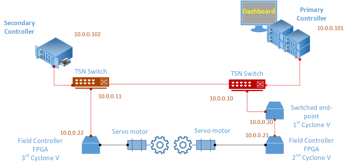
In practical terms, you need to do some mechanical setup, which is described in the subsequent sections. This setup uses different applications instantiated on the Cyclone V nodes as these nodes also need to read and write into the motor drive. The rest remains the same as in the previous setups, including the Industrial PCs (IPCs) and their configuration, the daisy-chain element, first Cyclone V board, and the switches and their configuration.
Setup Four: Hardware Bill of Materials
The following is the hardware used for the NGSF demo. If you use other hardware, you may need to do additional configuration steps that are not described in this section.
Two IPCs. The demo setup uses Kontron* models.
Three Cyclone® V SoC Development Kits and Intel® SoC FPGA Embedded Development Suite
Two Terasic Tandem Motion-Power 48V board
Two HSMC Flex Cable (shown in black)
One PC with Linux. The demo setup uses Ubuntu* 20.04
Six network cables (shown in red in the figure)
Two TSN switches: TTTech* Edge IP Solution board
Setup Four: Software Bill of Materials
Intel® Edge Controls for Industrial
main_ctrl_appsec_ctrl_appsec_ctrl_fpga_apptsn_dashboardConfiguration files for IPC nodes
Configuration files for TSN switches
Configuration files for Cyclone V
Cyclone V Linux Stack. For details on how to generate this stack, contact Intel Programmable Solutions Group Support, using “Contact us” on the webpage.
Script files
Ubuntu 20.04
Setup Four: Preparation
Follow the same steps presented in Setup Three: Assembly. The table with the IP addresses is the same as the one built for the previous setup.
End Node |
TSN IP (Interface) |
Management Network (Interface) |
Node ID |
|---|---|---|---|
Ubuntu Box |
10.0.0.2 (eth0) |
-1 |
|
TSN Switch |
10.0.0.10 |
||
Primary Controller |
10.0.0.101 (eth1) |
192.168.0.101 (not used) |
0 |
Secondary Controller |
10.0.0.102 (TBD) |
1 |
|
First Cyclone V |
10.0.0.20 (SE01) |
4 |
|
Second Cyclone V |
10.0.0.21 (SE01) |
5 |
|
Third Cyclone V |
10.0.0.22 (SE01) |
6 |
Copy the sec_ctrl_motor_app application to both Cyclone V boards attached to the motor kits. Make sure that you do not overwrite the ngsf.json file as it is already configured as needed.
Setup Three: Mechanical Assembly
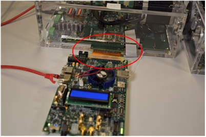
Start by connecting one end of the HSMC flex cable to a motor kit, and the other end to the Cyclone V development board. Repeat this on the other kit, as shown in the following figure.
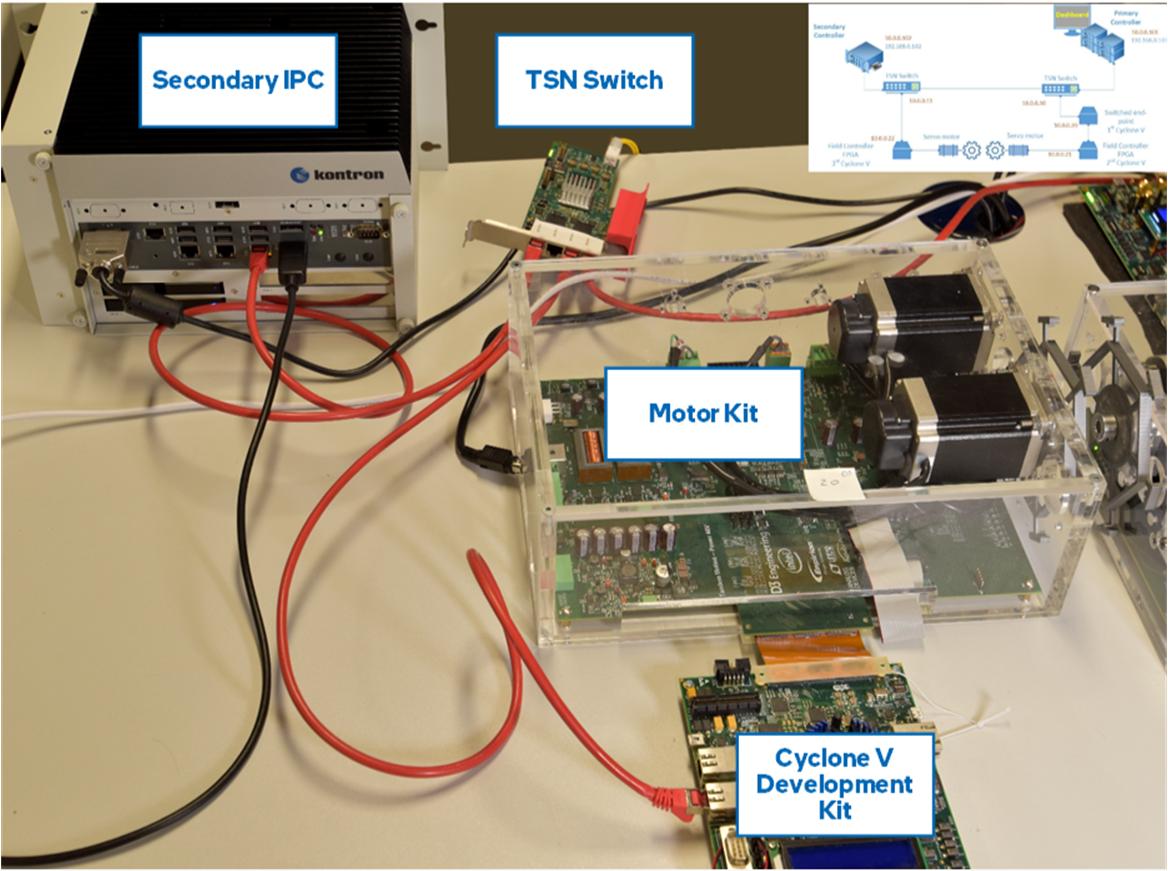
The following figure shows the left side of the setup, which includes the Secondary controller, TSN switch, the motor kit and Cyclone V development Kit connected to the motor kit.
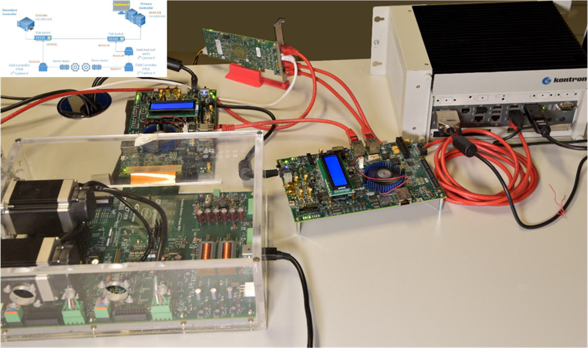
The following figure shows the right side of the setup, which includes the Primary controller, the TSN Switch, the Cyclone V as daisy chain element and as Field controller, and the motor kit.
To assemble the wheels, you need to start the Cyclone V applications. Both motors will be at the default positions, reducing the need for tuning the position through input parameters.
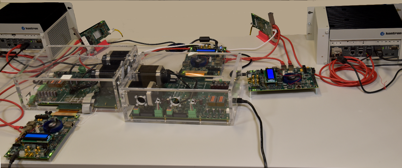
The following image shows the full setup. Two IPCs from Kontron are on the right and left sides. In the middle, there are two motor kits, with a Cyclone V development kit board linked to each kit. On the left, another Cyclone V development kit is connected as a daisy chain element, and the two TTTech DE boards are in the lower corner.
Setup Four: Setting up Discs
To set up the discs, turn ON the motor kits and the Cyclone V boards attached to it. Next, connect to both Cyclone V boards attached to the motor Kits and run the following command to start the application:
./sec_ctrl_motor_app
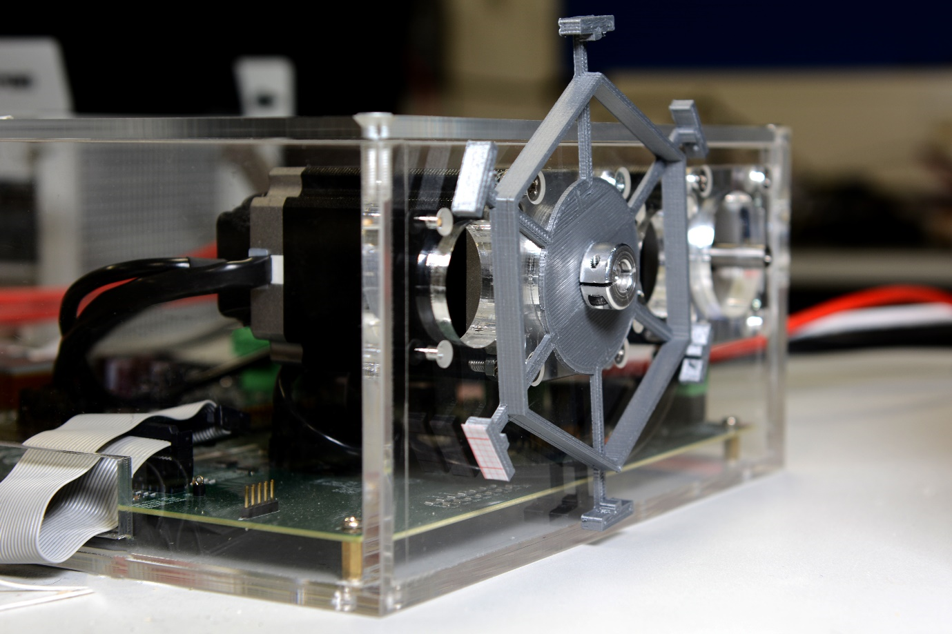
The motors will stop waiting to be controlled. This is the time to glue the disks. Every motor kit comes with a ring with a screw as shown in the following figure. Add glue to this ring and the disk with the holes aligned. Now, gently insert it into the motor axis and screw the ring into the axis. Make sure that the disk is fixed into the ring and the ring is screwed down, as shown in the figure.
Repeat the same procedure for the second disk.
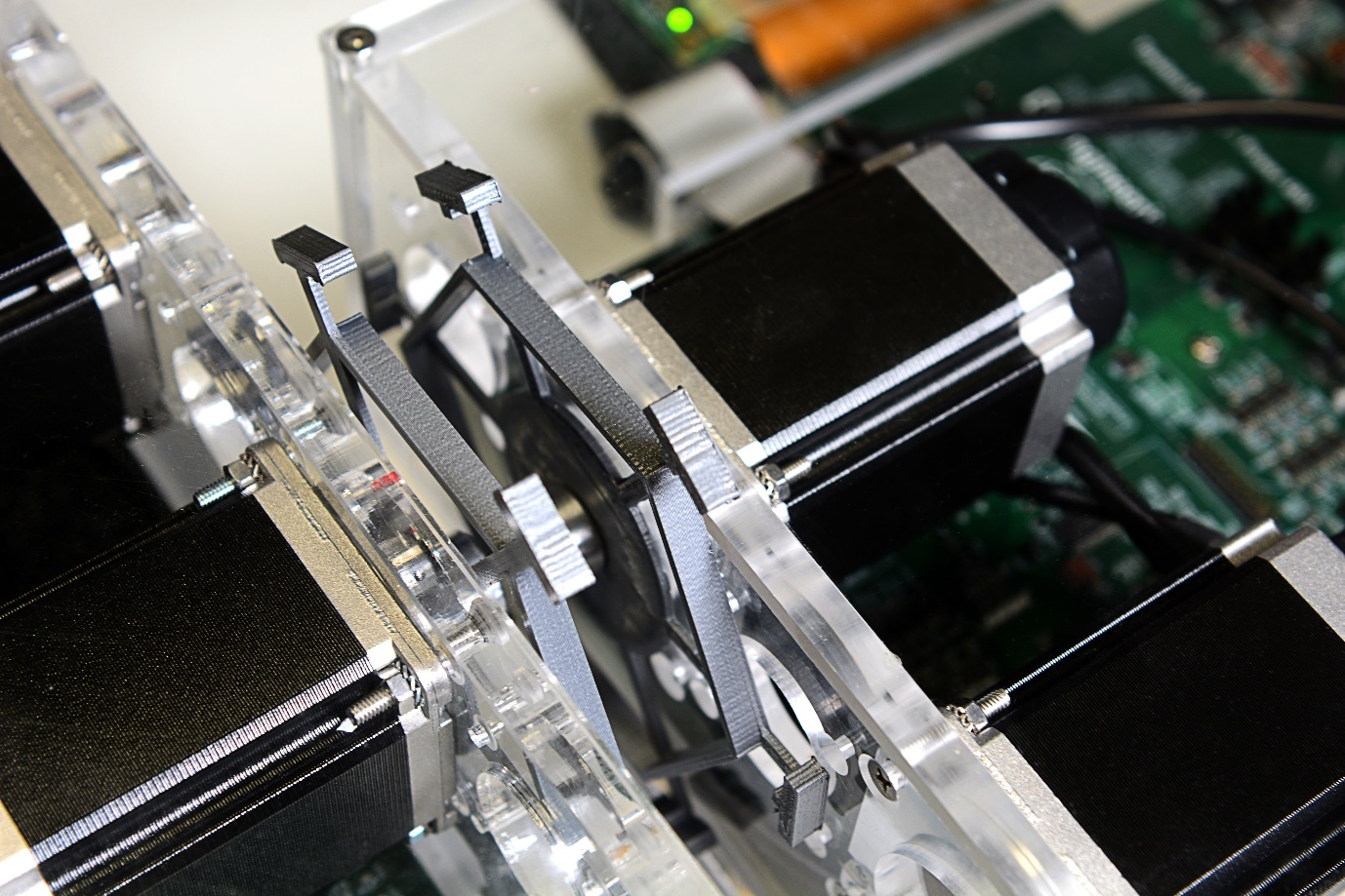
When fixing the disk, make sure that the shafts of both disks are aligned as shown in the following figure.
Setup Four: Running the Applications
Despite the similarity to the previous setup, the Cyclone V machines attached to the motor kits need a different application. This section describes the full startup of the system.
On the Primary controller, run the following commands:
cd app
./main_ctrl_app
Similarly, on the Secondary controller, run the following commands:
cd app
./sec_ctrl_app
On the Cyclone machines attached to the motor, run the following commands:
cd app
./sec_ctrl_motor_app ngsf.json
Optionally, you can collect KPIs from the daisy chain by connecting to the daisy chain element and running the following command:
cd app
./sec_ctrl_fpga_app ngsf.json
On the Linux box, run the following commands:
cd app
sudo ./tsn_dashboard
By default, traces should appear on the dashboard. Use the Preferences tab to customize the fields that must be plotted for the live data and long-term graphs.
Run the following commands to stop the applications at any time:
killall -9 main_ctrl_app
killall -9 sec_ctrl_app
Similarly, run the following command to kill the applications on Cyclone V:
killall -9 sec_ctrl_fpga_app
 killall -9 sec_ctrl_motor_app