Setup One
In this setup, a TSN switch is added to the Ground Zero setup, providing more ways to use the core functionality provided by NGSF and allowing comparison between different nodes.
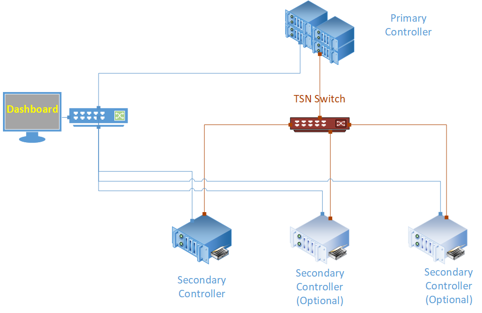
This setup is composed of one primary node and up to three secondary nodes. As in the Ground Zero setup, a separate computer is used to run the TSN dashboard and a management network.
This setup allows a runtime comparison between the secondary nodes, as the nodes are connected to the same switch and under the same conditions while are running the same application. The following figure shows the real-time communication network in red and the management network in blue.
Setup One: Hardware Bill of Materials
The following is the hardware used for the NGSF demo. If you use other hardware, you may need to do additional configuration steps that are not described in this section.
Two IPCs. The demo setup uses Kontron* models.
Secondary controllers, maximum two additional for total of three
One regular Ethernet switch
One PC with Linux. The demo setup uses Ubuntu* 20.04.
Four network cable (shown in red in the figure)
Five network cables (shown in blue in the figure)
Setup One: Software Bill of Materials
Intel® Edge Controls for Industrial
main_ctrl_app
sec_ctrl_app
tsn_dashboard
Configuration files for the IPC nodes
Configuration files for the TSN switch
Script files
Ubuntu 20.04
Setup One: Assembly
Start the assembly as indicated in Ground Zero: Assembly. As an additional step, configure the TSN switch by assigning an IP address to it.
After you complete the steps in Ground 0 – NGSF Foundation, the primary and secondary nodes will be configured. Disconnect the nodes and connect each node to the TSN switch in the middle. Next, configure the switch, such as the IP address to communicate and the gate control list. Follow the steps in the next section to configure the switch.
With this setup, to add and configure optional secondary nodes, perform the steps similar to the those in the Ground Zero setup when the secondary node was added.
Setup One: Interface Setup
Note: These steps assume that the TSN switch is a TTTech* Edge IP Solution board. If you use other hardware, you may need to do additional configuration not described in this guide.
As the first step, set the IP address of the TSN switch. You can connect to it using the default IP address via ssh, with the following command:
ssh root@192.168.0.1
If this connection does not work, you can connect to the switch via a serial cable connection. Once connected, set the IP address to 10.0.0.10/24 by editing the file /etc/network/interfaces:
auto SE01
iface SE01 inet static
address 10.0.0.10
netmask 255.255.255.0
If this command fails, refer to the manual of your TSN switch.
The second step is to configure the gate control list on the switch, which determines the time for opening and closing the gates for egress on the interfaces of the switch. Two files are provided: one is the default setup which leaves all gates open, and the other file contains the configuration for a point-to-point cycle of 500us.
As the TSN switch is not reachable from the management network, the configuration files must be copied temporarily to one of the nodes attached to the TSN switch. Assuming that the switch configuration files are already available on the end nodes when the configuration folder was copied, run the following command from one of the end nodes:
ssh root@10.0.0.10 ‘mkdir -p /root/config/’
scp -r config/switch/ root@10.0.0.10:/root/config/.
Connect to the switch and run the following command to configure the default gate control list (GCL):
$cd /root/config
$./setup_tttech default
To set GCL, run the following command:
$./setup_tttech NAME
You can set the GCL to default or tune for the TSN transmission at any time. For example, it can be set to default to show a partial effect of turning TSN OFF, all gates opened, and then you can set the GCL again to return to the initial state.
Since the initial objective of this NGSF setup is to enable communication, it is recommended that you use the default configuration.
This setup allows you to add more secondary nodes, as described below.
Similar to the secondary node configuration presented in section 5.2.3.1, first connect the blue cable to the regular network switch and configure the network interface using:
connmanctl services
Obtain the desired interface and run the following command:
connmanctl config ethernet_SECADMINMAC_cable --ipv4 manual 192.168.0.103 255.255.255.0
Connect the TSN interface from the newly added end node to the TSN switch and rerun the following command:
connmanctl services
Configure this new TSN interface by issuing the command:
connmanctl config ethernet_SECONDARYTSNMAC_cable --ipv4 manual 10.0.0.103 255.255.255.0
If you want to add another end node, use the IPs 192.168.0.104/24 and 10.0.0.104 for the management and TSN network, respectively. The following table summarizes the IP addresses and end nodes node IDs used in Setup 1, including the optional Secondary controllers. Note that the interface name must be recorded during configuration.
End Node |
TSN IP (Interface) |
Management Network (Interface) |
Node ID |
|---|---|---|---|
Ubuntu Box |
192.168.0.2 (eth0) |
-1 |
|
TSN Switch |
10.0.0.10 |
||
Primary Controller |
10.0.0.101 (eth1) |
192.168.0.101 (eth0) |
0 |
Secondary Controller |
10.0.0.102 (eth1) |
192.168.0.102 (eth0) |
1 |
Secondary Controller (Optional 1) |
10.0.0.103 (eth1) |
192.168.0.103 (eth0) |
2 |
Secondary Controller (Optional 2) |
10.0.0.104 (eth1) |
192.168.0.104 (eth0) |
3 |
The next step is to set the clocks of the IPCs with the switch, which is required for the synchronization applications to work. Remember that the clock synchronization algorithms work best when the time difference is minimal, however, having a few seconds of difference is acceptable to start the synchronization process. It is recommended to set the clock of the end nodes according to the clock of the switch, because this is a best-known method to achieve clock synchronization.
To do so, open a console for each end node and a console to the switch. Remember that to open one shell to the switch, you must first open a terminal for one of the end nodes, because the TSN switch is not accessible on the management network.
Start at the switch and run the following command:
date
The expected output:
Tue Oct 10 22:55:01 PDT 2017
Next, set the end nodes. On each end node, run the following command:
date -s “Tue Oct 10 22:55:01 PDT 2017”
hwclock -w
Now it is possible to start the clock synchronization at the end nodes. On the TTTech switches, the synchronization daemon starts at boot time as a service. Independent of the number of end nodes, proceed as presented in Ground Zero: Preparation, controlling the outputs of ptp4l and phc2sys. Once clock synchronization is achieved, from the configuration folder, stop the process, and proceed with the full setup using the following commands:
cd $HOME/config
stop_sync
setup_host
For completeness, check the ptp4l and phc2sys logs again. At this point, all end nodes are ready to run TSN applications. However, you still need to do some additional configuration.
Setup One: Application Configuration
If you have not added an end node to the Ground Zero setup, that is, there is only one secondary node, the applications should be ready to run. For completeness, a new node will be added to clearly demonstrate what needs to be done.
On the Linux development desktop or the PC running the dashboard, create a copy the ngsf.json file and name it as ngsf2.json. This new configuration file will be used to change the configuration for the newly added secondary node. In the new file, change the interfaces for the sec_ctrl_app according to the values recorded in the above table. Then, copy this file to the newly added secondary node along with the application as done in the already configured secondary node.
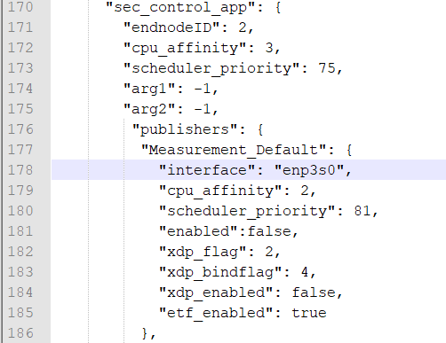
If there are more Secondary controllers, the endnodeID field of sec_control_app must be changed. Every end node must have a unique number in the setup. The node ID must be changed in the ngsf.json file as shown in the following figure.
Setup One: Running the Applications
Now that you have everything configured, it is time to run the applications.
Copy the following:
main_ctrl_appto theappfolder of the Primary controllersec_ctrl_appto theappfolder of the Secondary controllertsn_dashboardto the Linux systemngsf.jsonfile to the same folder containingmain_ctrl_app,sec_ctrl_app, andtsn_dashboard
If you have added any new secondary nodes, copy sec_ctrl_app and the ngsf.json file modified for that node to the app folder.
On the Primary controller, run the following command:
cd app
NGSFDBG=”True” ./main_ctrl_app
Similarly, run the following command on the Secondary controller:
cd app
NGSFDBG=”True” ./sec_ctrl_app
On the Linux system, run the following command:
cd app
sudo ./tsn_dashboard
By default, traces should appear on the dashboard. Use the Preferences tab to customize the fields that must be plotted for the live data and long-term graphs.
Run the following commands to stop the applications at any time:
killall -9 main_ctrl_app
killall -9 sec_ctrl_app
The next section presents the Key Performance Indicators (KPIs) that are valid and can be used with this setup.
Setup One: Key Performance Indicators
Following are the Key Performance Indicators (KPIs) captured with this setup.
Min/Max/Ave Rx Jitter
Min/Max/Ave E2E latency
Min/Max/Ave Rx cycle
Min/Max/Ave Phc2sys time diff
Min/Max/Ave Read Sys Clock latency
Min/Max/Ave Read Ph Clock latency
Number of lost packets
As servomotors are not included in this setup yet, the corresponding measurements are not present.
To review the extensive list of indicators present in the NGSF demo, refer to OPC UA Messaging.