IgH EtherCAT Master Stack
The EtherCAT master stack by IgH* is used for open source projects for automation of systems such as Robot Operating System (ROS) and Linux* CNC. Applications of an open source–based EtherCAT master system reduces cost and makes application program development flexible. Based on the native, Intel® made the following optimizations:
Support Linux* Kernel 5.x
Support Xenomai* 3 and Preempt RT
Migrate Operation thread to Xenomai Dovetail
Migrate latest IGB/IGC driver to stack
Install IgH EtherCAT Master Stack
You can install this component from the ECI APT repository. Setup the ECI APT repository, then perform either of the following commands to install this component:
- Install from meta-package
$ sudo apt install eci-softplc-fieldbus
- Install from individual Deb packages
# For non-Xenomai kernels
$ sudo apt install ighethercat ighethercat-dkms ighethercat-examples ecat-enablekit

# For Xenomai kernels
$ sudo apt install ighethercat ighethercat-dkms ighethercat-examples-xenomai ecat-enablekit-xenomai
Set up EtherCAT Master
This section describes the procedure to run IgH EtherCAT Master Stack on Intel® Edge Controls for Industrial (Intel® ECI or ECI).
Dependencies
Native EtherCAT Device Driver - IGB (High performance)
Only supports IGB and IGC devices (Intel® Ethernet Controller I210, Intel® Ethernet Controller I211, Intel® Ethernet Controller I225)
One networking driver for EtherCAT and non-EtherCAT devices
Driver gets more complicated, as it must handle EtherCAT and non-EtherCAT devices.
Generic EtherCAT Device Driver - Generic (Low performance) - Any Ethernet hardware that is covered by a Linux Ethernet driver can be used for EtherCAT - Performance is low compared to the native approach, because the frame data have to traverse the lower layers of the network stack
Note: If the target system does not support the IGB device driver, select the generic EtherCAT device driver.
System Integration
The following section is applicable to:

EtherCAT Initialization Script
The EtherCAT master init script is installed in /etc/init.d/ethercat.
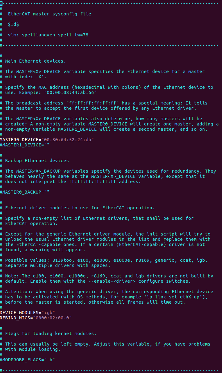
EtherCAT Sysconfig File
The init script uses a mandatory sysconfig file installed in /etc/sysconfig/ethercat. The sysconfig file contains the configuration variables needed to operate one or more masters. The documentation is within the file and also included here.
Do the following:
Set REBIND_NICS. Use
lspcito query net devices. One of the devices might be be specified as an EtherCAT network interface.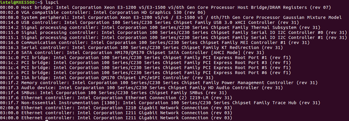
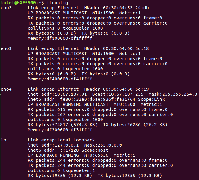
Fill the MAC address for MASTER0_DEVICE. Get the MAC address of the Network Interface Controllers (NICs) selected for EtherCAT.
Modify DEVICE_MODULES:
Option 1: Intel Corporation I210 GbE controller EtherCAT driver (High performance)
DEVICE_MODULES="igb"
Option 2: Intel Corporation I225 GbE controller EtherCAT driver (High performance)
DEVICE_MODULES="igc"
Option 3: Intel® Core™ 12th S-Series [Alder Lake] and 11th Gen P-Series and U-Series [Tiger Lake] Intel® Atom™ x6000 Series [Elkhart Lake] GbE controller EtherCAT driver (High performance)
DEVICE_MODULES="dwmac_intel"
Fallback: Generic driver as EtherCAT driver (Low performance)
DEVICE_MODULES="generic"
Start Master as Service
After the init script and the sysconfig file are ready to configure, and are placed in the right location, the EtherCAT master can be inserted as a service. You can use the init script to manually start and stop the EtherCAT master. Execute the init script with one of the following parameters:
Start EtherCAT Master
Stop EtherCAT Master
Restart EtherCAT Master
Status of EtherCAT Master
Multi-Axis Synchronization System (MASS)
The following figure shows the setup of Multi-Axis Synchronization System (MASS).
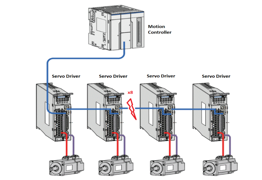
This system setup includes motion controller, servo driver, motors, and software. The Motion Controller is an Intel-based system with ECI enabled. The Motion Controller connects eight servo drivers. The system runs a program to control six servos motors (three pairs) simultaneously through EtherCAT to control pencil leads to rotate and move horizontally and vertically.
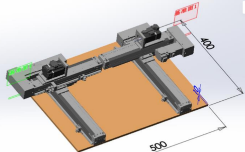
Two other servos motors are controlled simultaneously through EtherCAT to draw a circle.
Test binary will be released in /opt/ighethercat/examples/ec_multi_axis_example.
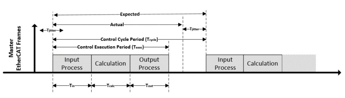
EtherCAT Control Loop and Time Measurement
EtherCAT Sanity Checks
The following section is applicable to:
Sanity Check #1: EtherCAT Master Start
Start EtherCAT Master:
$ /etc/init.d/ethercat start

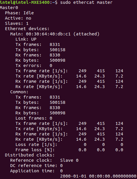
Check Master information:
$ ethercat master
Expected output
Sanity Check #2: EtherCAT Master Scan
The following section is applicable to:
Start EtherCAT Master:
$ /etc/init.d/ethercat start
Scan EtherCAT Slave:
$ ethercat rescan
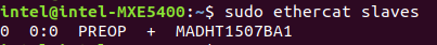
Check slaves on the bus:
$ ethercat slaves
Expected output
Sanity Check #3: MASS Platform Performance Collection
Use EtherCAT network cable to connect the MASS platform and the Controller, in specific the EtherCAT network interface. Power up the MASS platform.
Start EtherCAT Master:
$ /etc/init.d/ethercat start
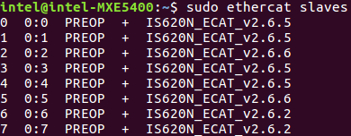
Check EtherCAT bus to make sure that eight EtherCAT slaves are scanned and stay on PREOP status.
$ ethercat slaves
Expected output
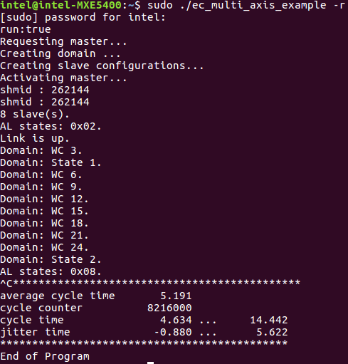
Start
/opt/ighethercat/examples/ec_multi_axis_example -rto collect real-time performance:$ /opt/ighethercat/examples/ec_multi_axis_example -r
Expected output
Tip
Useful command parameters:
-r      Motor start running
-t      Set measure time for minutes, default is no time limitation
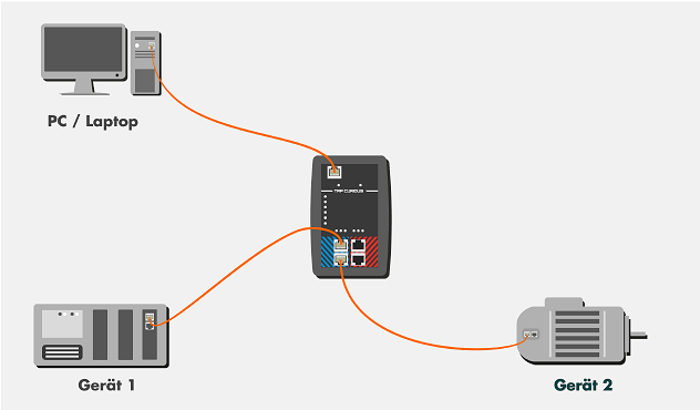
EtherCAT Analysis with Wireshark
Hardware Setup
Software Setup
Start the IgH EtherCAY+T master stack.
Start the EtherCAT IO sample code:
$ /opt/ighethercat/examples/ec_ecatdio_example -t 100
Note: Useful command parameter:
-t Set horse light cycle tick
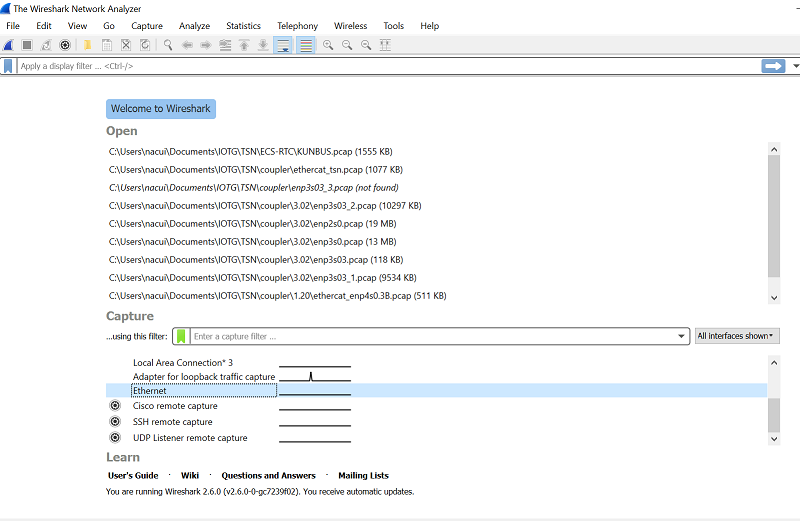
Capture EtherCAT Packets with Wireshark
The Wireshark main window lists all available Ethernet interfaces. Click the required Ethernet interface to select it.
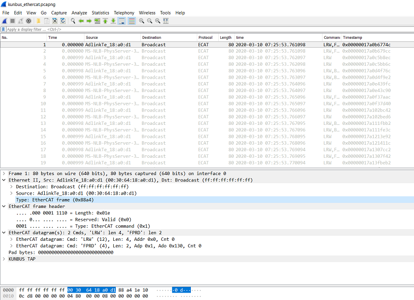
Use Wireshark to analyze the data.
Note: If ECAT packets are not captured, disable security software.
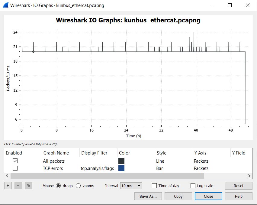
The following is a sample I/O graph.
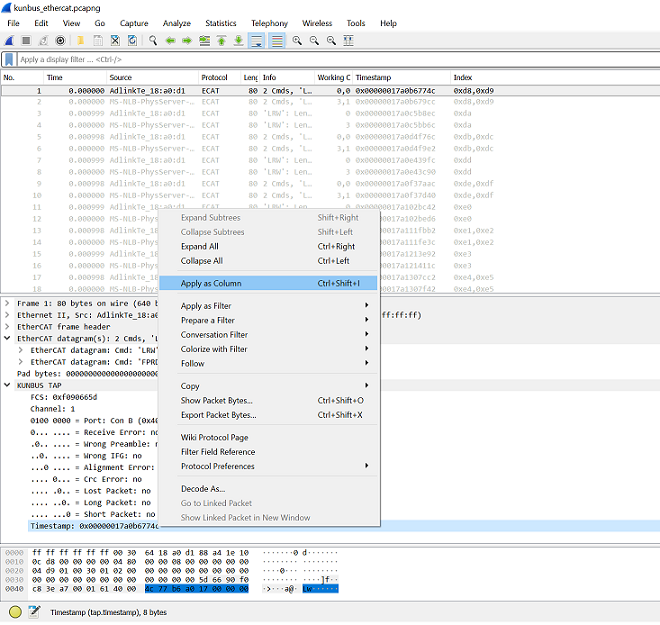
Jitter Analysis by Wireshark
Find the timestamp in KUNBUS TAP and apply it as column.
Filter the packets from master.
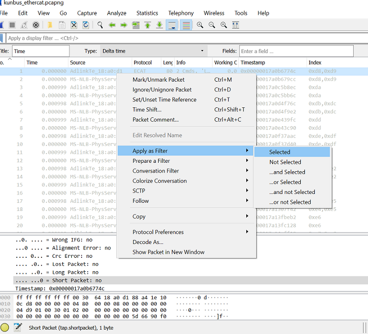
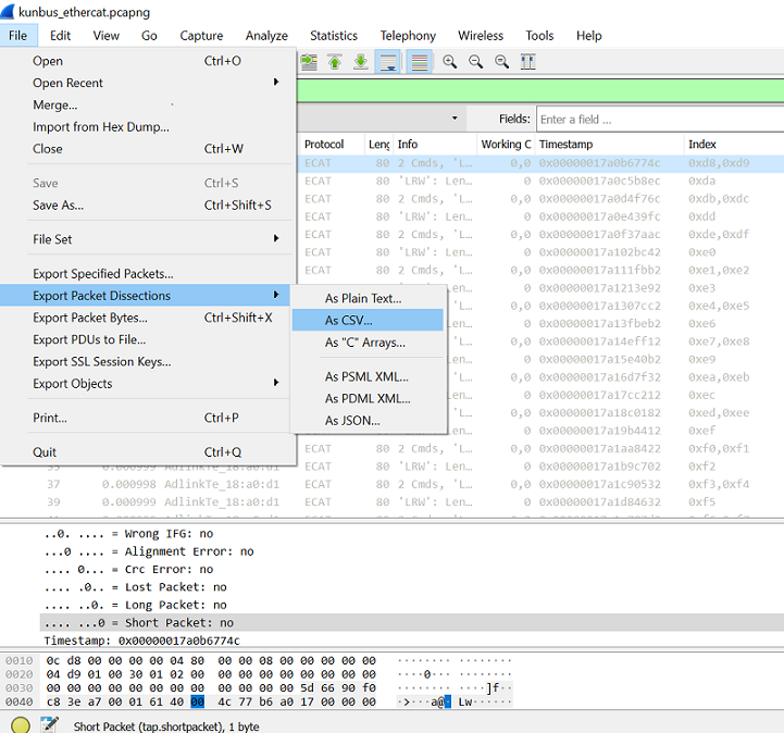
Export the data to .csv format.
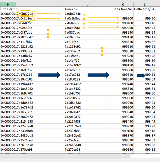
Open the data file, using Microsoft Excel, and find the timestamp column. Retrieve the last nine digits (in ns) and then calculate the delta time between two cycles.
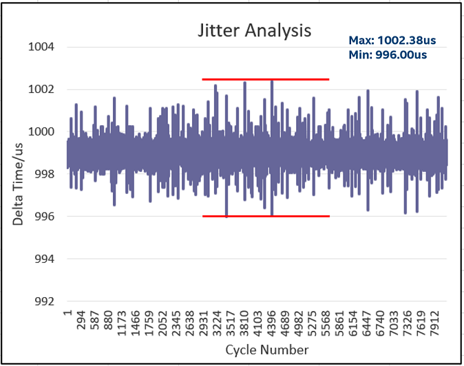
Plot the delta time graph and note the jitter +/-4us within 1ms per cycle.
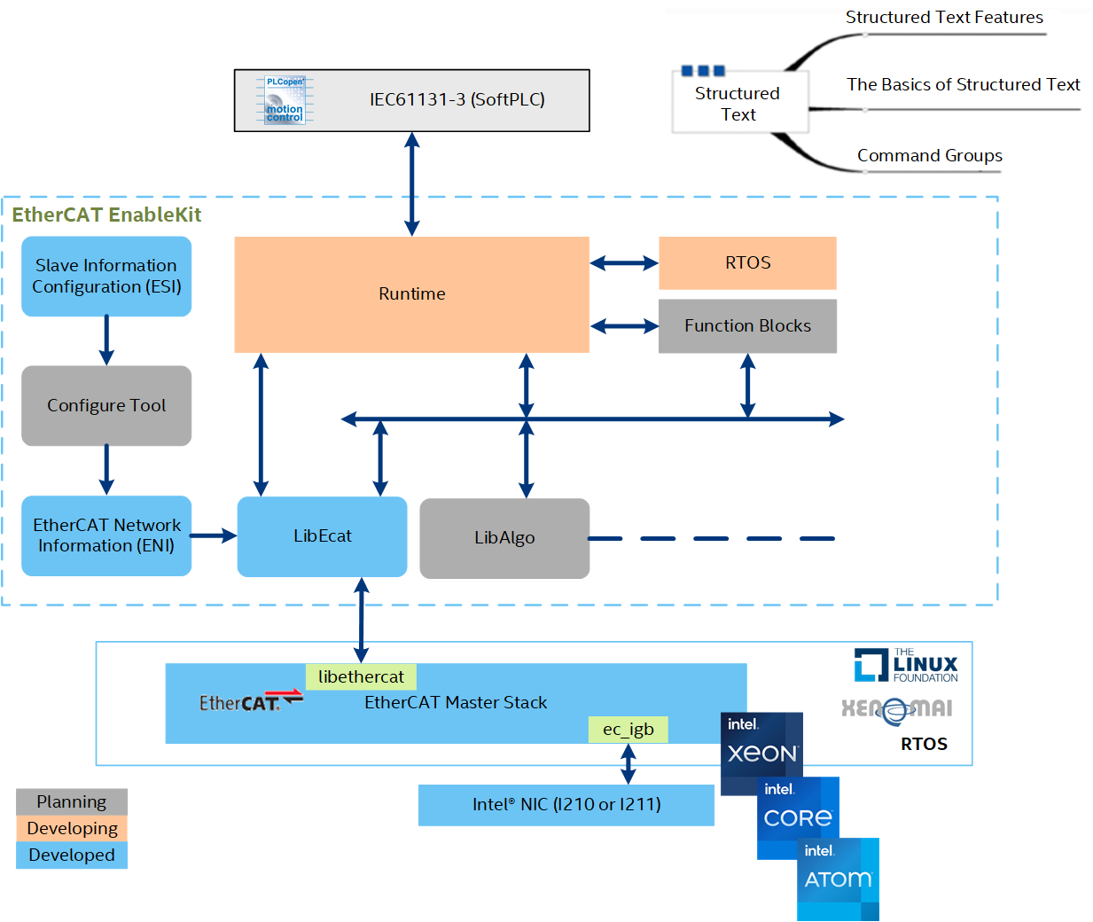
EtherCAT Enablekit
EtherCAT Enablekit Overview
EtherCAT EnableKit provides tools that simplify the process of customizing the configurations of EtherCAT master, slave, and network topology. It provides APIs to develop EtherCAT application programs easily. With EtherCAT EnableKit, developers can focus on what is truly important and leave the tedious configuration process to the system.
EtherCAT EnablekitFeatures
Based on this version, the following features are included:
Is based on IgH EtherCAT Master Stack
Supports Preempt-RT and Xenomai
Includes functions to parse EtherCAT Network Information (ENI)
Includes functions to parse EtherCAT Slave Information (ESI)
Provides APIs to develop EtherCAT application program easily
Provides example code to driver EtherCAT IO slaves
Provides example code to driver EtherCAT CoE slaves (SOE is not currently supported)
EtherCAT Enablekit Code Sample
EtherCAT Enablekit Requirements
The software can run on commodity PC or Server. The software is developed primarily in C language, so it should be straightforward to port to other operating systems.
EtherCAT Enablekit Sanity Checks
The following section is applicable to:
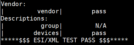
Sanity Check #1: ESI Parsing
Navigate to the
/opt/ecat-enablekitdirectory:$ cd /opt/ecat-enablekit
Test the ESI file, for example
esi_xxx.xml, with option -s:$ ./test-motion -s esi_xxx.xml
Expected output
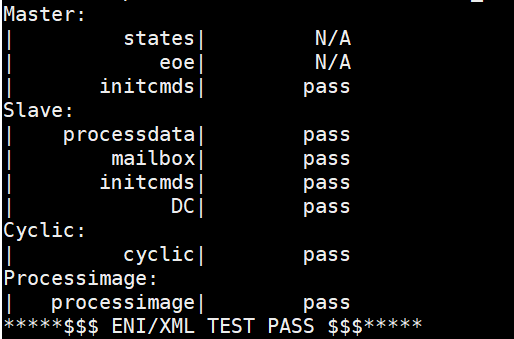
Sanity Check #2: ENI Parsing
Navigate to the
/opt/ecat-enablekitdirectory:$ cd /opt/ecat-enablekit
Test the ENI file, for example,
eni_xxx.xml, with option -n:$ ./test-motion -n eni_xxx.xml
Expected output
Real-Time Vision with EtherCAT
The real-time vision provides a deterministic way to complete synchronization between motion control and image capture even when the object is moving at a high speed. The stopping time can be saved, thus improving efficiency and productivity.
The key to achieving the synchronization is the time-aware IO. An EtherCAT IO with timestamping can be utilized to trigger a deterministic capturing for an accurate image. You can also apply Time-aware GPIO by following the guidelines in Intel TCC Tools - Enable Linux Time-Aware GPIO. Then, machine vision can process the accurate image to provide precise position offset and angle offset for next-step motion control.
Usage Case
The following figure shows an example of a SMT production line.
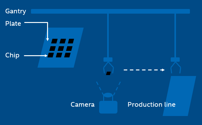
In the SMT production line, the gantry with a sucker sucks a chip from the plate and then mounts on the PCB. However, it is not always able to hit the expected point and the expected angle of the chip during the suction.
Even little shift can lead to deviation, making it impossible to mount the chip in the right place eve later. After image capturing, the machine vision helps to compute position/angel offset value of the chip for perfect mounting.
In the traditional way, the gantry will stop above the camera and wait for a while for image capturing. This is not necessary when applying real-time vision, thus improving efficiency significantly.
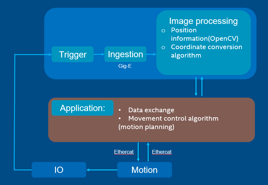
Work Flow
The application controls the motion by EtherCAT and synchronizes with IO. When reaching the target timing, IO will trigger the camera to capture an image. The image is then processed with machine vision to provide the position value and the angel value. By data exchange, the application continues the motion control with position information.
Solution Principle
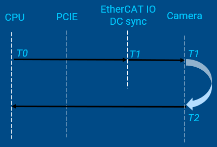
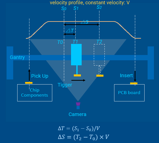
T0is the time when CPU sends shooting commandS0is the position to prepare trigger shooting, which can be read in cyclic task. It corresponds toT0T1is the time to trigger the picture shootingS1is the expected fixed position to trigger shooting△Tcan be calculated with∆𝑇=(𝑆_1−𝑆_0)/𝑉T2is the time when the image is captured on CMOSS2reflects the real position where the image is capturing.The time between
T2andT1is used for camera exposure and image generatingReal-time vision should make the time intervals
(T2 - T1)and(T1 – T0)deterministic
Example Demonstration
The demo code is integrated into IgH EtherCAT stack components as an example and is in /usr/src/ighethercat-dkms-1.5.2/examples/fly_trigger_poc.