Real Time Vision
The real-time vision provides a deterministic way to complete synchronization between motion control and image capture even the objective is in high-speed moving. Then the stopping time can be saved, thus to improve efficiency and productivity.
The key to achieve the synchronization is the time-aware IO. And an EtherCAT IO with timestamping can be utilized to trigger a deterministic capturing for an accurate image. Then the accurate image can be processed by machine vision to provide precise position offset and angle offset for next-step motion control.
Usage case
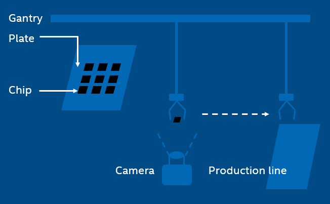
In the SMT production line, this kind of operation is always shown, that the gantry with a sucker sucks a chip from the plate and then mounts on the PCB. But it’s not always able to hit the expected point and the expected angle of the chip during the suction. Even little shift can lead to deviation, so that the chip cannot be mounted in the right place later. Then the machine vision does help after the image capturing, to computer position/angel offset value of the chip for perfect mounting.
In the tradition way, the gantry will stop above the camera and wait for a while for image capturing. Now is not necessary anymore when applying real-time vision. And the efficiency can be improved significantly.
Work Flow
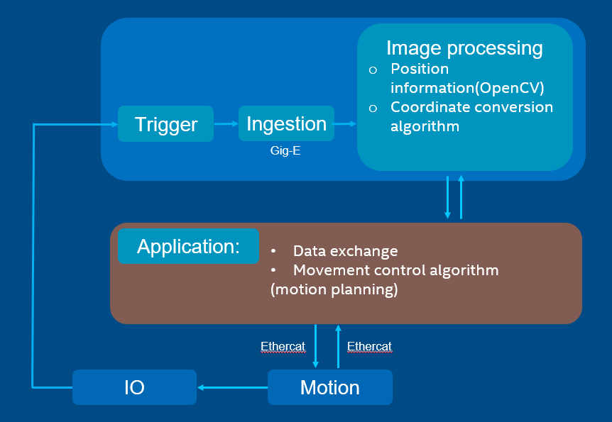
The application controls the motion by EtherCAT and synchronizes with IO. When reaching the target timing, IO will trigger the camera to capture an image. And then the image will be processed with machine vision to provide the position value and the angel value. By data exchanging, the application continues the motion control with position information.
Solution principle
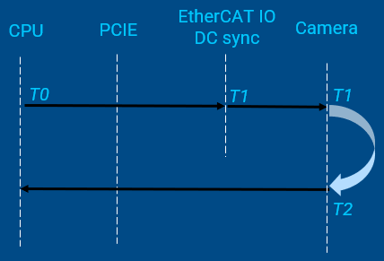
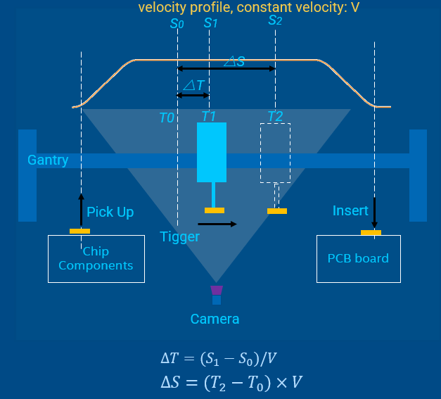
T0is the time when CPU sends shooting commandS0is the position to prepare trigger shooting, which can be read in cyclic task. It corresponds toT0.T1is the time to trigger the picture shootingS1is the expected fixed position to trigger shooting.△Tcan be calculated with∆𝑇=(𝑆_1−𝑆_0)/𝑉T2is the time when the image is captured on CMOSS2reflects the real position where the image is capturing.The time between
T2andT1is used for camera exposure and image generatingReal-time vision should make the time intervals
(T2 - T1)and(T1 – T0)deterministic
Demo example
The demo code is integrated into IgH EtherCAT stack components as an example in examples/fly_trigger_poc